How to Configure IPSec Site-to-Site VPN Tunnel on OPNsense?
IPSec is a collection of communication protocols that provide secure connections over a network. The phrase "IPsec" is an abbreviation where "IP" represents "Internet Protocol" and "sec" represents "secure." Internet Protocol (IP) is the universally accepted protocol that governs the transmission of data over the Internet. IPSec enhances the security of the protocol by including encryption and authentication. It is used in virtual private networks (VPNs).
OPNsense provides VPN connectivity for both branch offices and remote users (Road-Warrior). Setting up a single, secure private network that connects several branch offices to a central location is simply accomplished using the OPNsense web user interface. Certificates may be generated and invalidated for distant users, and a user-friendly export tool simplifies the client configuration process.
Site-to-site VPNs VPNs connect two locations and route traffic between their respective networks through the use of static public IP addresses. This is typically employed to establish a connection between the branch offices and the main office of an organization, allowing branch users to retrieve network resources located in the main office.
This guide will explain the process of configuring an IPsec site-to-site VPN tunnel using an OPNsense firewall. You may easily configure IPsec site-to-site VPN tunnel by following 9 main steps:
- Configuring Firewall Rules on Both Site
- Configuring Phase 1 on Site-A
- Configuring Phase 2 on Site-A
- Enabling IPsec on Site-A
- Configuring Phase 1 on Site-B
- Configuring Phase 2 on Site-B
- Enabling IPsec on Site-B
- Adding Firewall Rule for LAN Access on Both Site
- Viewing IPsec Tunnel Status

Sample IPsec Site-to-Site VPN Topology
In this tutorial, the following IP addresses will be used for the sites that connect to each other via an IPsec VPN tunnel:
| Option | Value |
|---|---|
| Hostname | SiteA_FW |
| WAN IP | 11.11.11.1/32 |
| LAN Net | 10.10.10.0/24 |
| LAN IP | 10.10.10.1/24 |
| LAN DHCP Range | 10.10.10.100-10.10.10.200 |
Table 1. IP settings on Site A OPNsense Firewall
| Option | Value |
|---|---|
| Hostname | SiteB_FW |
| WAN IP | 11.11.11.2/32 |
| LAN Net | 10.10.11.0/24 |
| LAN IP | 10.10.11.1/24 |
| LAN DHCP Range | 10.10.11.100-10.10.11.200 |
Table 2. IP settings on Site B OPNsense Firewall

Figure 1. IPsec site-to-site VPN Topology
1. Configuring Firewall Rules on Both Site
To allow IPsec Tunnel Connections, the following ports should be accessible from the Internet on WAN interfaces for both sites.
- UDP Traffic on Port 4500 (NAT-T)
- UDP Traffic on Port 500 (ISAKMP)
- Protocol ESP
You may easily add firewall rules on OPNsense firewalls located in Site A and Site B by following the next steps:
- Allowing ESP port access from the Internet
- Allowing IPSec NAT-T port access from the Internet
- Allowing ISAKMP port access from the Internet
1. Allowing ESP Protocol access from the Internet
Firewall rule settings required for ESP protocol access are given in the next table:
| Option | Value |
|---|---|
| Action | Pass |
| Interface | WAN |
| Protocol | ESP |
| Source | any |
| Source Port | any |
| Destination | WAN address |
| Destination Port | any |
| Category | IPsec Tunnel |
| Description | Allow ESP for IPsec Tunnel |
Table 3. Firewall rule settings for ESP protocol access
You may easily add firewall rules to allow ESP protocol access for IPsec connection on OPNsense firewalls located in Site A and Site B by following the next steps:
-
Navigate to the WAN interface on the Firewall Rules.
-
Select Pass for the allow rule.
-
Select ESP as the Protocol.
-
Select
anyas the source. -
Select
anyas the source port. -
Select
anyas type. -
Select WAN address as the destination.
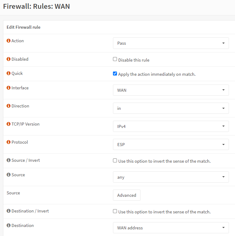
Figure 2. Defining firewall rule for ESP access-1
-
Set Category to
IPsec Tunnel. -
Set Description to
Allow ESP for IPsec Tunnel. -
Enable Log packets that are handled by this rule option.
-
Click Save.
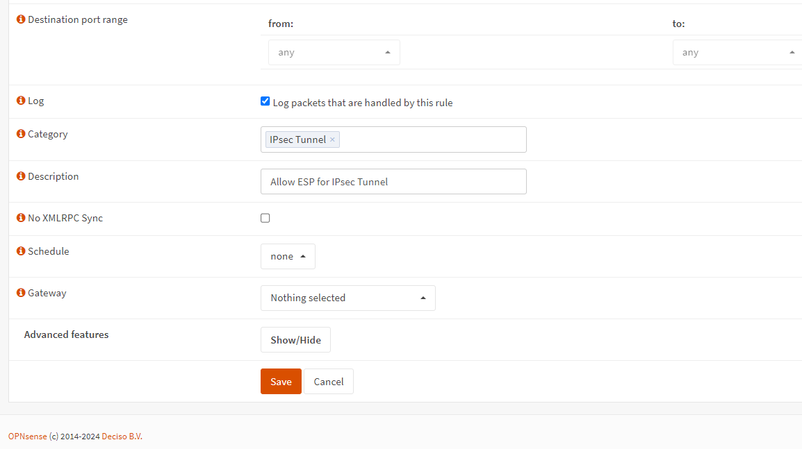
Figure 3. Defining firewall rule for ESP access-2
2. Allowing IPsec NAT-T port access from the Internet
Firewall rule settings required for IPSec NAT-T port access are given in the next table:
| Option | Value |
|---|---|
| Action | Pass |
| Interface | WAN |
| Protocol | UDP |
| Source | any |
| Source Port | any |
| Destination | WAN address |
| Destination Port Range | IPsec NAT-T |
| Category | IPsec Tunnel |
| Description | Allow IPsec NAT-T for IPsec Tunnel |
Table 4. Firewall rule settings for IPSec NAT-T port access
You may easily add firewall rules to allow IPsec NAT-T port access for IPsec connection on OPNsense firewalls located in Site A and Site B by following the next steps:
-
Navigate to the WAN interface on the Firewall Rules.
-
Select Pass for the allow rule.
-
Select UDP as the Protocol.
-
Select
anyas the source. -
Select
anyas the source port. -
Select
anyas type. -
Select WAN address as the destination.
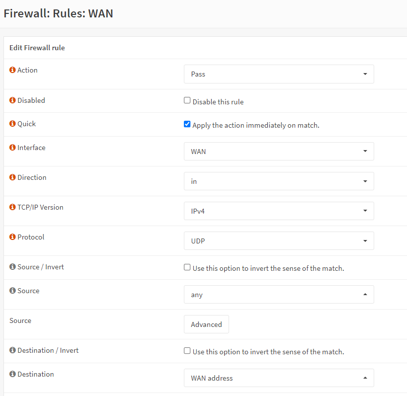
Figure 4. Defining firewall rule for IPsec NAT-T access-1
-
Select
IPsec NAT-Tas the destination port range. -
Set Category to
IPsec Tunnel. -
Set Description to
Allow IPsec NAT-T port for IPsec Tunnel. -
Enable Log packets that are handled by this rule option.
-
Click Save.

Figure 5. Defining firewall rule for IPsec NAT-T port access-2
3. Allowing ISAKMP port access from the Internet
Firewall rule settings required for ISAKMP port access are given in the next table:
| Option | Value |
|---|---|
| Action | Pass |
| Interface | WAN |
| Protocol | UDP |
| Source | any |
| Source Port | any |
| Destination | WAN address |
| Destination Port Range | ISAKMP |
| Category | IPsec Tunnel |
| Description | Allow ISAKMP for IPsec Tunnel |
Table 5. Firewall rule settings for ISAKMP port access
You may easily add firewall rules to allow ISAKMP port access for IPsec connection on OPNsense firewalls located in Site A and Site B by following the next steps:
-
Navigate to the WAN interface on the Firewall Rules.
-
Select Pass for the allow rule.
-
Select UDP as the Protocol.
-
Select
anyas the source. -
Select
anyas the source port. -
Select
anyas type. -
Select WAN address as the destination.
-
Select
ISAKMPas the destination port range. -
Set Category to
IPsec Tunnel. -
Set Description to
Allow ISAKMP port for IPsec Tunnel. -
Enable Log packets that are handled by this rule option.
-
Click Save.
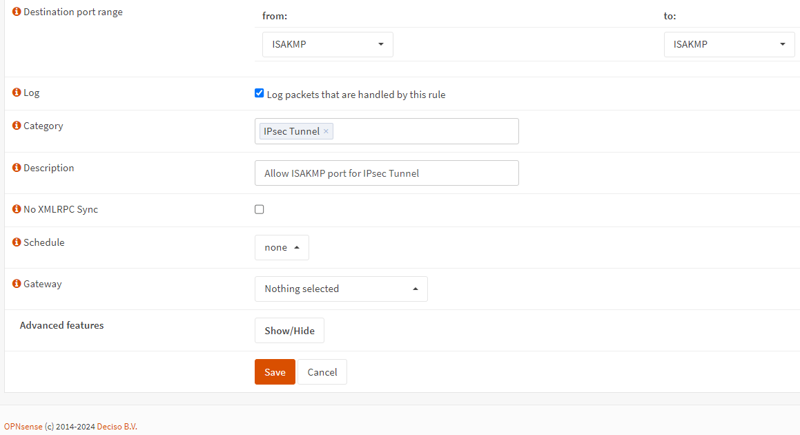
Figure 6. Defining firewall rule for ISAKMP port access
After added these 3 firewall rules on both OPNsense firewalls located on SiteA and SiteB, click Apply Changes button to activate the new settings.
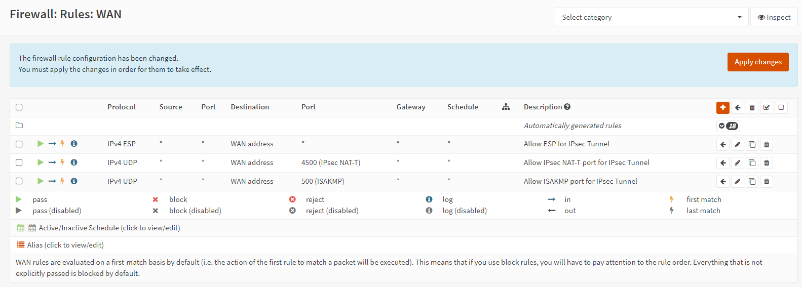
Figure 7. Applying firewall rules for IPsec Tunnel
2. Configuring Phase 1 on Site-A
General Phase-1 options on Site-A are given in the next table.
| Option | Value | Description |
|---|---|---|
| Connection method | default | default is "Start on traffic" |
| Key Exchange version | V2 | |
| Internet Protocol | IPv4 | |
| Interface | WAN | choose the interface connected to the internet |
| Remote gateway | 11.11.11.2 | the public IP address of your remote OPNsense |
| Description | Site B | freely chosen description |
Table 6. General Information Phase-1 options for Site-A
Authentication Phase-1 options on Site-A are given in the next table.
| Option | Value | Description |
|---|---|---|
| Authentication method | Mutual PSK | Using a Pre-shared Key |
| My identifier | My IP address | Simple identification for fixed ip |
| Peer identifier | Peer IP address | Simple identification for fixed ip |
| Pre-Shared Key | MyS2SIPSecTunnel | Random key. You should create your own one. |
Table 7. Authentication Phase-1 options for Site-A
Phase 1 proposal (Algorithms) options on Site-A are given in the next table.
| Option | Value | Description |
|---|---|---|
| Encryption algorithm | 256-bit AES-GCM with128-bit ICV | For our sample we will use 256-bit AES-GCM with128-bit ICV |
| Hash algoritm | SHA512 | Use a strong hash like SHA512 |
| DH key group | 14 (2048 bit) | 2048 bit should be sufficient |
| Lifetime | 28800 sec | lifetime before renegotiation |
Table 8. Phase 1 proposal (Algorithms) Phase-1 options for Site-A
Advanced Phase-1 options on Site-A are given in the next table.
| Option | Value | Description |
|---|---|---|
| Disable Rekey | Unchecked | Renegotiate when connection is about to expire |
| Disable Reauth | Unchecked | For IKEv2 only re-authenticate peer on rekeying |
| NAT Traversal | Disabled | For IKEv2 NAT traversal is always enabled |
| Dead Peer Detection | Unchecked |
Table 9. Advanced Phase-1 options for Site-A
You may easily configure IPSec Phase-1 on Site-A by following the next steps:
-
Navigate to the VPN → IPSec → Tunnel Settings on Site-A OPNsense web UI.
-
Click Add button with
+at the right bottom of the Phase 1 pane. -
Enter the public IP address or hostname of the Remote Gateway, such as
11.11.11.2. -
Enter a Description for your reference, such as
Site B. -
You may leave other options as default in General information pane.
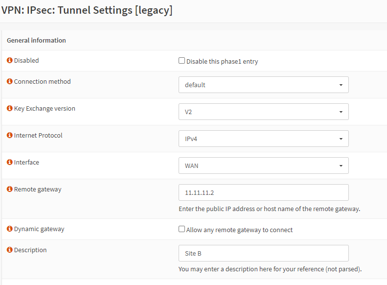
Figure 8. General Information for Phase-1 on Site-A
-
Enter your Pre-Shared Key string., such as
MyS2SIPSecTunnel. -
You may leave other options as default in the Phase 1 proposal (Authentication) pane.
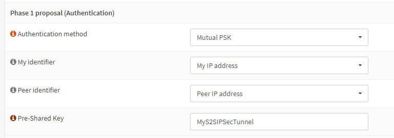
Figure 9. Phase 1 proposal (Authentication) on Site-A
-
Select Encryption algorithm, such as
256-bit AES-GCM with128-bit ICV. -
Select Hash algorithm, such as
SHA512. -
Select DH key group, such as
14 (2048) bits. This option must match the setting chosen on the remote side.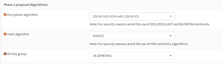
Figure 10. Algorithms Phase 1 options on Site-A
-
Set NAT Traversal to
Disablein Advanced Options pane. -
Click Save.
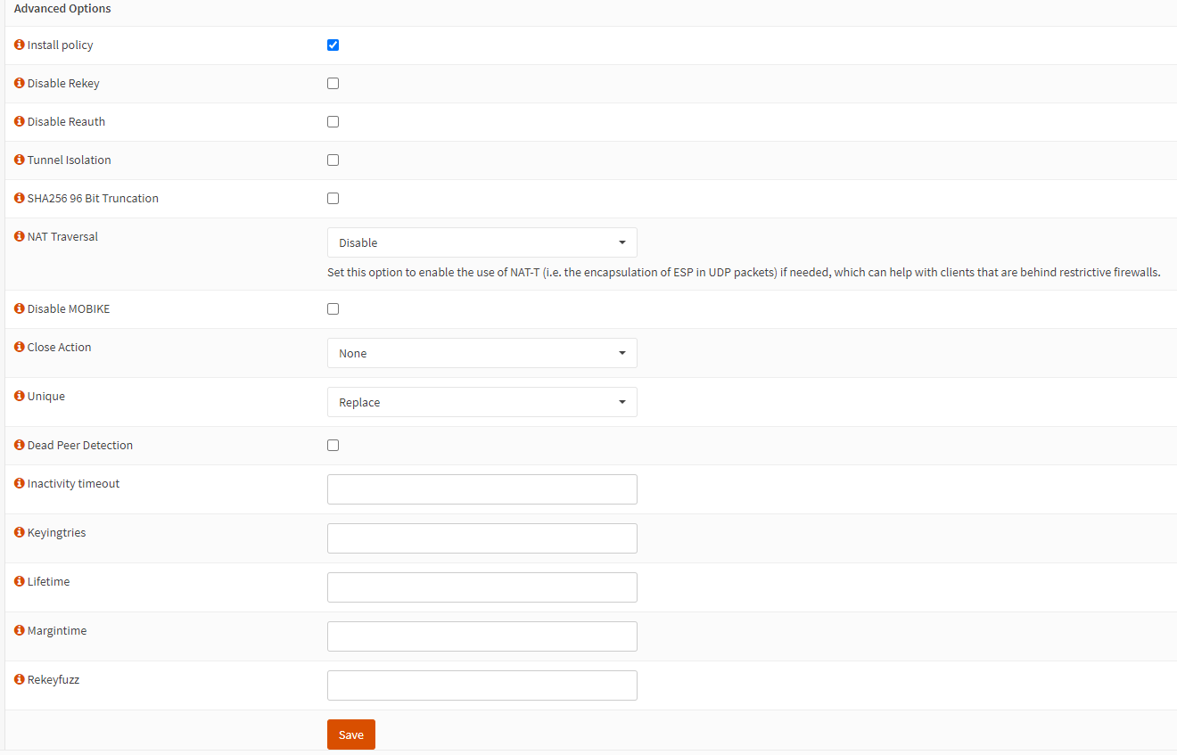
Figure 11. Advanced Phase 1 options on Site-A
3. Configuring Phase 2 on Site-A
General Information Phase-2 options on Site-A are given in the next table.
| Option | Value | Description |
|---|---|---|
| Mode | Tunnel IPv4 | Select Tunnel mode |
| Description | Local LAN Site B | Freely chosen description |
Table 10. General Information Phase-2 options on Site-A
Local Network Phase-2 options on Site-A are given in the next table.
| Option | Value | Description |
|---|---|---|
| Local Network | LAN subnet | Route the local LAN subnet |
Table 11. Local Network Phase-2 options on Site-A
Remote Network Phase-2 options on Site-A are given in the next table.
| Option | Value | Description |
|---|---|---|
| Type | Network | Route a remote network |
| Address | 10.10.11.0/24 | The remote LAN subnet |
Table 12. Remote Network Phase-2 options on Site-A
Phase 2 proposal (SA/Key Exchange) options on Site-A are given in the next table.
| Option | Value | Description |
|---|---|---|
| Protocol | ESP | Choose ESP for encryption |
| Encryption algorithms | AES256GCM16 | For the sample we use AES256GCM16 |
| Hash algortihms | SHA512 | Choose a strong hash like SHA512 |
| PFS Key group | 14 (2048 bit) | Not required but enhanced security |
| Lifetime | 3600 sec |
Table 13. Phase 2 proposal (SA/Key Exchange) on Site-A
You may easily configure IPSec Phase-1 on Site-A by following the next steps:
-
Navigate to the VPN → IPSec → Tunnel Settings on Site-A OPNsense web UI.
-
Click add phase 2 entry button with
+at the Commands column of the recently added phase 1 entry.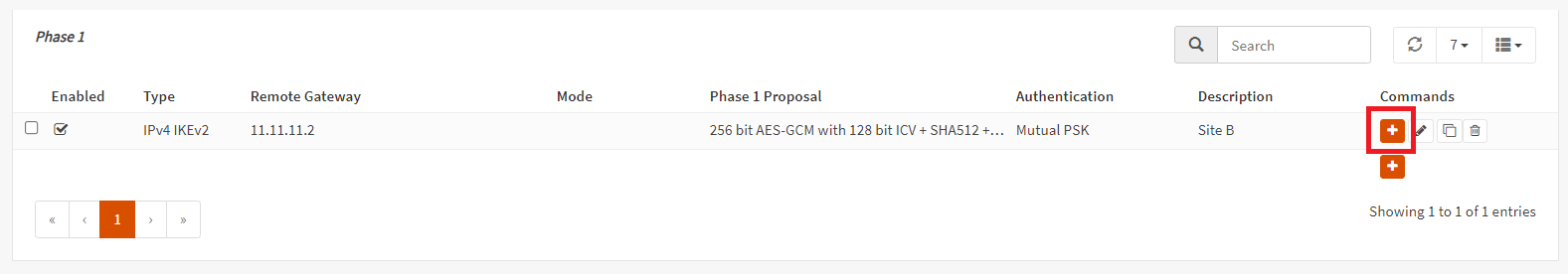
Figure 12. Adding Phase-2 Entry
-
Add a Description, such as
Local LAN Site B. -
Set Address option for Remote Network, such as
10.10.11.0/24.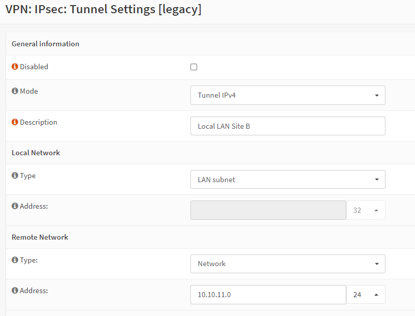
Figure 13. General Information for Phase-2 on Site-A
-
Select Encryption algorithms, such as
AES256GCM16. -
Select Hash algorithms, such as
SHA512. -
Select PFS key group, such as
14 (2048) bits. -
Set Lifetime, such as
3600. -
You may leave other options as default.
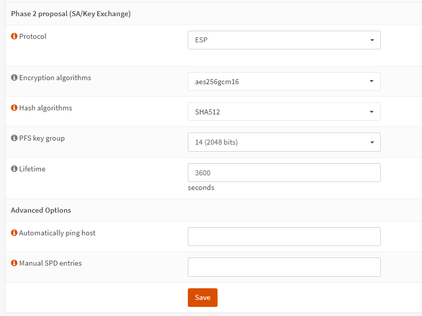
Figure 14. Algorithms for Phase-2 on Site-A
-
Click Save.
-
Click the checkbox at the beginning of the Phase 1 pane to view the Phase 2 settings.
4. Enabling IPsec on Site-A
You may quickly enable IPsec service on SIte-A by following the next steps:
-
Navigate to the VPN → IPSec → Tunnel Settings on Site-A OPNsense web UI.
-
Check Enable IPsec option at the bottom of the page.
-
Click Apply Changes button at the top right corner of the page to activate the IPsec tunnel settings.
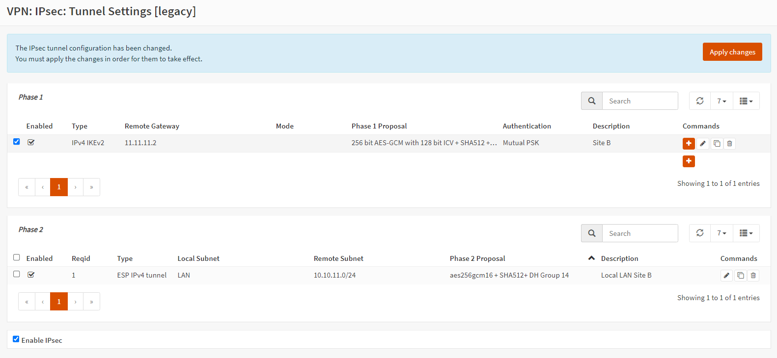
Figure 15. Enabling IPsec on Site-A
5. Configuring Phase 1 on Site-B
General Phase-1 options on Site-B are given in the next table.
| Option | Value | Description |
|---|---|---|
| Connection method | default | default is "Start on traffic" |
| Key Exchange version | V2 | |
| Internet Protocol | IPv4 | |
| Interface | WAN | choose the interface connected to the internet |
| Remote gateway | 11.11.11.1 | the public IP address of your remote OPNsense |
| Description | Site A | freely chosen description |
Table 14. General Phase-1 options on Site-B
Authentication Phase-1 options on Site-B are given in the next table.
| Option | Value | Description |
|---|---|---|
| Authentication method | Mutual PSK | Using a Pre-shared Key |
| My identifier | My IP address | Simple identification for fixed ip |
| Peer identifier | Peer IP address | Simple identification for fixed ip |
| Pre-Shared Key | MyS2SIPSecTunnel | Random key. You should create your own. |
Table 15. Authentication Phase-1 options on Site-B
Phase 1 proposal (Algorithms) options on Site-B are given in the next table.
| Option | Value | Description |
|---|---|---|
| Encryption algorithm | 256-bit AES-GCM with128-bit ICV | For our sample we will Use AES/256 bits |
| Hash algoritm | SHA512 | Use a strong hash like SHA512 |
| DH key group | 14 (2048 bit) | 2048 bit should be sufficient |
| Lifetime | 28800 sec | lifetime before renegotiation |
Table 16. Algorithms Phase-1 options on Site-B
Advanced Phase-1 options on Site-B are given in the next table.
| Option | Value | Description |
|---|---|---|
| Disable Rekey | Unchecked | Renegotiate when connection is about to expire |
| Disable Reauth | Unchecked | For IKEv2 only re-authenticate peer on rekeying |
| NAT Traversal | Disabled | For IKEv2 NAT traversal is always enabled |
| Dead Peer Detection | Unchecked |
Table 17. Advanced Phase-1 options on Site-B
You may easily configure IPSec Phase-1 on Site-B by following the next steps:
-
Navigate to the VPN → IPSec → Tunnel Settings on Site-A OPNsense web UI.
-
Click Add button with
+at the right bottom of the Phase 1 pane. -
Enter the public IP address or hostname of the Remote Gateway, such as
11.11.11.1. -
Enter a Description for your reference, such as
Site A. -
You may leave other options as default in General information pane.
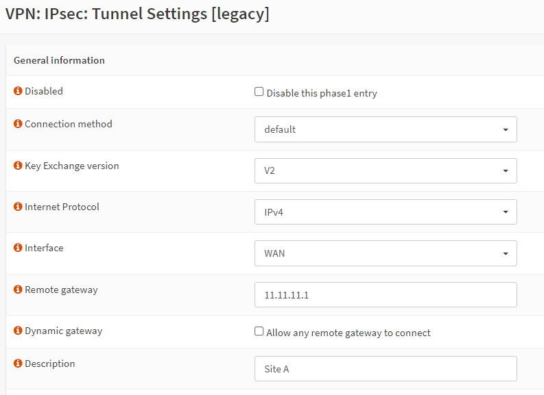
Figure 16. General information Phase-1 on Site-B
-
Enter your Pre-Shared Key string., such as
MyS2SIPSecTunnel. -
You may leave other options as default in the Phase 1 proposal (Authentication) pane.
-
Select Encryption algorithm, such as
256-bit AES-GCM with128-bit ICV. -
Select Hash algorithm, such as
SHA512. -
Select DH key group, such as
14 (2048) bits. This option must match the setting chosen on the remote side. -
Set NAT Traversal to
Disablein Advanced Options pane. -
Click Save.
6. Configuring Phase 2 on Site-B
General Information Phase-2 options on Site-B are given in the next table.
| Option | Value | Description |
|---|---|---|
| Mode | Tunnel IPv4 | Select Tunnel mode |
| Description | Local LAN Site A | Freely chosen description |
Table 18. General Information Phase-2 options on Site-B
Local Network Phase-2 options on Site-B are given in the next table.
| Option | Value | Description |
|---|---|---|
| Local Network | LAN subnet | Route the local LAN subnet |
Table 19. Local Network Phase-2 options on Site-B
Remote Network Phase-2 options on Site-B are given in the next table.
| Option | Value | Description |
|---|---|---|
| Type | Network | Route a remote network |
| Address | 10.10.10.0/24 | The remote LAN subnet |
Table 20. Remote Network Phase-2 options on Site-B
Phase 2 proposal (SA/Key Exchange) options on Site-B are given in the next table.
| Option | Value | Description |
|---|---|---|
| Protocol | ESP | Choose ESP for encryption |
| Encryption algorithms | AES256GCM16 | For the sample we use AES256GCM16 |
| Hash algortihms | SHA512 | Choose a strong hash like SHA512 |
| PFS Key group | 14 (2048 bit) | Not required but enhanced security |
| Lifetime | 3600 sec |
Table 21. Phase 2 proposal (SA/Key Exchange) Phase-2 options on Site-B
You may easily configure IPSec Phase-2 on Site-B by following the next steps:
-
Navigate to the VPN → IPSec → Tunnel Settings on Site-B OPNsense web UI.
-
Click add phase 2 entry button with
+in the Commands column of the recently added phase 1 entry. -
Add a Description, such as
Local LAN Site A. -
Set Address option for Remote Network, such as
10.10.10.0/24.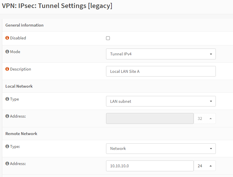
Figure 17. General information Phase-2 on Site-B
-
Select Encryption algorithms, such as
AES256GCM16. -
Select Hash algorithms, such as
SHA512. -
Select PFS key group, such as
14 (2048) bits. -
Set Lifetime, such as
3600. -
You may leave other options as default.
-
Click Save.
-
Click the checkbox at the beginning of the Phase 1 pane to view the Phase 2 settings.
7. Enabling IPsec on Site-B
You may quickly enable IPsec service on SIte-B by following the next steps:
-
Navigate to the VPN → IPSec → Tunnel Settings on Site-B OPNsense web UI.
-
Check Enable IPsec option at the bottom of the page.
-
Click Apply Changes button at the top right corner of the page to activate the IPsec tunnel settings.
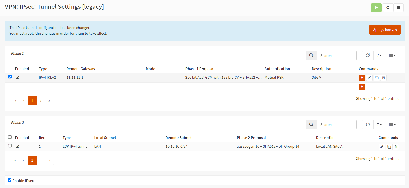
Figure 18. Enabling IPsec on Site-B
8. Adding Firewall Rule for LAN Access on Both Site
You may easily add firewall rules on OPNsense firewalls located in Site A and Site B by following the next steps to allow IPsec tunnels to access LAN:
| Option | Value |
|---|---|
| Action | Pass |
| Interface | IPsec |
| Protocol | any |
| Source | any |
| Source Port | any |
| Destination | LAN net |
| Destination Port | any |
| Category | IPsec Tunnel |
| Description | Allow IPsec Tunnel traffic to LAN |
Table 22. Firewall rule settings for LAN access
-
Navigate to the IPsec interface on the Firewall Rules.
-
Select
Passfor the allow rule. -
Select
anyas the Protocol. -
Select
anyas the Source. -
Select
anyas the Source port. -
Select
anyas Type. -
Select LAN net as the destination.
-
Set Category to
IPsec Tunnel. -
Set Description to
Allow IPsec Tunnel traffic to LAN. -
Enable Log packets that are handled by this rule option.
-
Click Save.
-
Click Apply Changes.
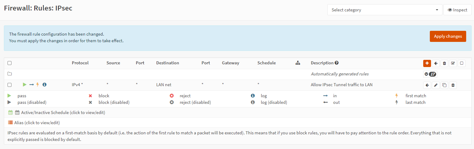
Figure 19. Firewall rule for LAN access on IPsec interface
9. Viewing IPsec Tunnel Status
Both networks should now be routed through the tunnel. To view the current IPsec VPN tunnel status, you may follow navigate to VPN → IPsec → Status Overview on OPNsense web UI.
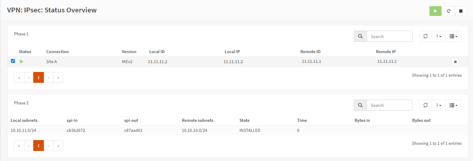
Figure 20. Viewing IPsec Tunnel Status
Attempt a service restart on both endpoints if the tunnel fails to appear.
How to Troubleshoot IPsec S2S Tunnel Problems on OPNsense
You can navigate through the configured tunnels using the VPN → IPsec → Status Overview menu in order to monitor the connected tunnels.
Additionally, it is possible to gain insight into the registered policies by navigating to the VPN → IPsec → Security Association Database; when NAT is in place, the additional SPD entries should also be visible here.
When attempting to diagnose issues with your OPNsense firewall, you will almost certainly be required to examine the records that are accessible on your system. The user interface of OPNsense organizes log files in accordance with the configurations of the component to which they pertain. The location of the log files is specified in the "Log file" menu.
The most common IPsec site-to-site tunnel issues and their solutions explained below:
-
Phase 1 does not come up: That issue is quite challenging. Before proceeding, verify that the WAN interface is permitted on the appropriate ports and protocols (ESP, UDP 500, and UDP 4500) via the firewall.
Examine your IPSec log to determine whether this is a potential cause.
Inequality in settings is a prevalent concern. Both endpoints must employ the identical PSK and encryption protocol.
-
Phase 1 is operational, but phase 2 tunnels are not connected: Have the proper local and remote networks been configured? It is a frequent error to enter the IP address of the remote host rather than the network's
x.x.x.0suffix.Inequality in settings is a prevalent concern. Both endpoints must employ the identical encryption protocol.
How to Tune IPsec Tunnel on OPNsense?
Enabling multithreaded crypto mode on IPsec is advantageous, depending on the burden (single flow or multiple IPsec flows). This mode distributes cryptographic packets across multiple processors, which is particularly beneficial when only one tunnel is in use.
To enable multithreaded crypto mode on IPsec, you may add or modify the following tunable by navigating to System → Settings → Tunables on OPNsense UI.
net.inet.ipsec.async_crypto = 1