How to Configure Transparent Filtering Bridge on OPNsense?
A transparent firewall filters traffic without requiring the creation of separate subnets. This firewall is referred to as filtering bridge because it functions as a bridge between two interfaces and implements filtering rules on top of this. In this tutorial, we will explain you how to configure your OPNsense firewall as a transparent filtering bridge.
There is incompatibility between the Transparent Filtering Bridge and Traffic Shaping. When utilizing the filtering bridge, do not activate the traffic shaper.
As a starting point for this tutorial, we need a basic installation of OPNsense with 3 interfaces:
-
WAN interface
-
LAN interface
-
LAN Management interface
We will use the LAN management interface to access the OPNsense node for administration purposes. WAN and LAN interfaces will be configured as the members of the bridge interface.

Figure 1. OPNsense Transparent Filtering Bridge Topology
Zenarmor NGFW Plug-in for OPNsense is one of the most popular OPNsense plug-ins and allows you to easily upgrade your firewall to a Next Generation Firewall in seconds. NG Firewalls empower you to combat modern-day cyber attacks that are becoming more sophisticated every day.
Some of the capabilities are layer-7 application/user aware blocking, granular filtering policies, commercial-grade web filtering utilizing cloud-delivered AI-based Threat Intelligence, parental controls, and the industry's best network analytics and reporting.
Zenarmor Free Edition is available at no cost for all OPNsense users.
You can easily configure the Transparent Filtering Bridge on OPNsense firewall by following the next 10 steps explained below:
- Disable Outbound NAT rule generation
- Change system tuneables
- Create the Bridge
- Interface Assignment
- Disable Block Private & Bogon Networks
- Disable the DHCP Server on LAN
- Firewall Rule Configuration To Allow All Traffic
- Disable Default Anti Lockout Rule
- Set LAN and WAN interface type to none
- Adding Firewall Rules
1. Disable Outbound NAT rule generation
To disable outbound NAT, you may follow the steps given below:
-
Navigate to the Firewall → NAT → Outbound on your OPNsense UI.
-
Select "Disable Outbound NAT rule generation".
-
Click Save.
-
Click Apply Changes to activate the configuration.

Figure 2. Disable Outbound NAT on OPNsense Firewall
2. Change system tuneables
To enable filtering bridge, you must change net.link.bridge.pfil_bridge from default to 1 and change net.link.bridge.pfil_member from default to 0. To set To change these system tuneables, you may follow the steps given below:
-
Navigate to the System → Settings → Tuneables on OPNsense UI.
-
Use
CTRL+Fon your browser to find thenet.link.bridge.pfil_bridgein the list.
Figure 3. Editing net.link.bridge.pfil_bridge
-
Click on the Edit button with pen icon to set the
net.link.bridge.pfil_bridgetuneable. -
Set the Value option to
1and click Save to enable filtering on the bridge interface.Figure 4. Enable filtering on the bridge interface
-
Use
CTRL+Fon your browser to find thenet.link.bridge.pfil_memberin the list.
Figure 5. Editing net.link.bridge.pfil_member
-
Click on the Edit button with pen icon to set the
net.link.bridge.pfil_membertuneable. -
Set the Value option to
0and click Save to disable filtering on the members of bridge interface.Figure 6. Disabling filtering on bridge member interfaces
3. Create the Bridge
To create a bridge of LAN and WAN, you may follow the steps given below:
-
Navigate to Interfaces → Other Types → Bridge on OPNsense UI
-
Click on the
+Add button to create a new bridge interface.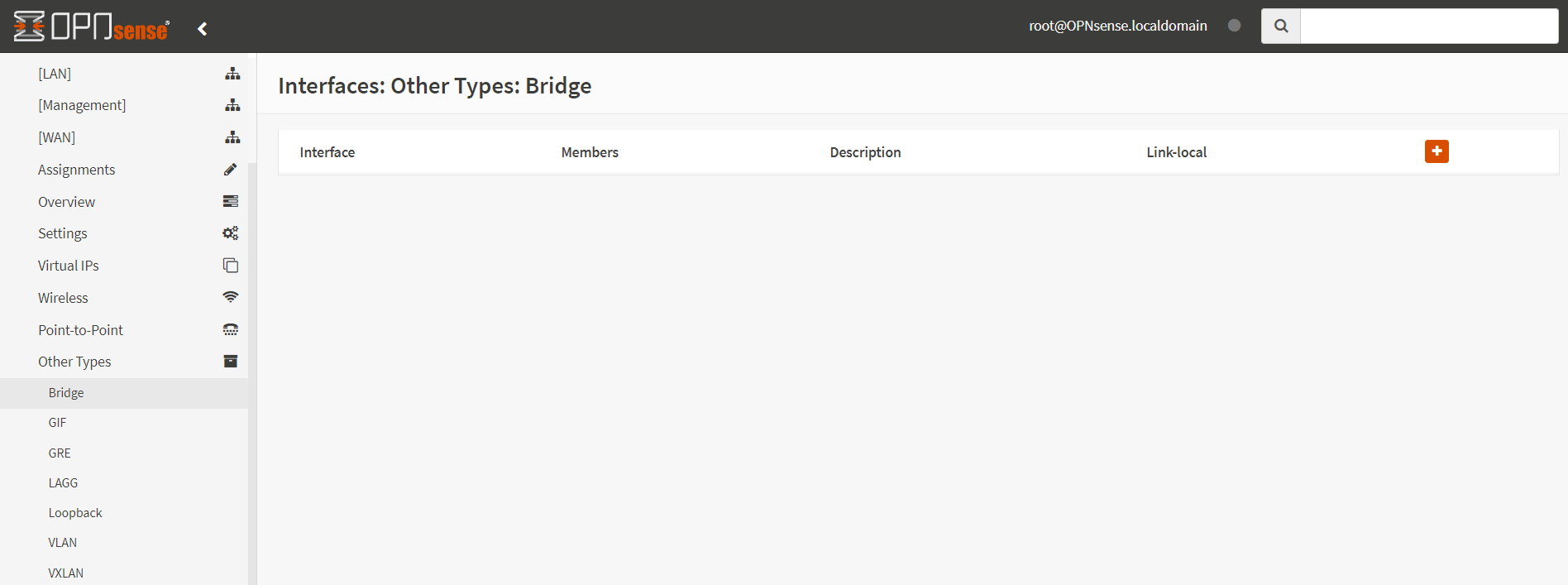
Figure 7. Adding a new bridge member interface
-
Select
LANandWANin the Member Interfaces drop-down menu.
Figure 8. Selecting member interfaces for a new bridge
-
Type a descriptive name, like
Bridgein the Description field.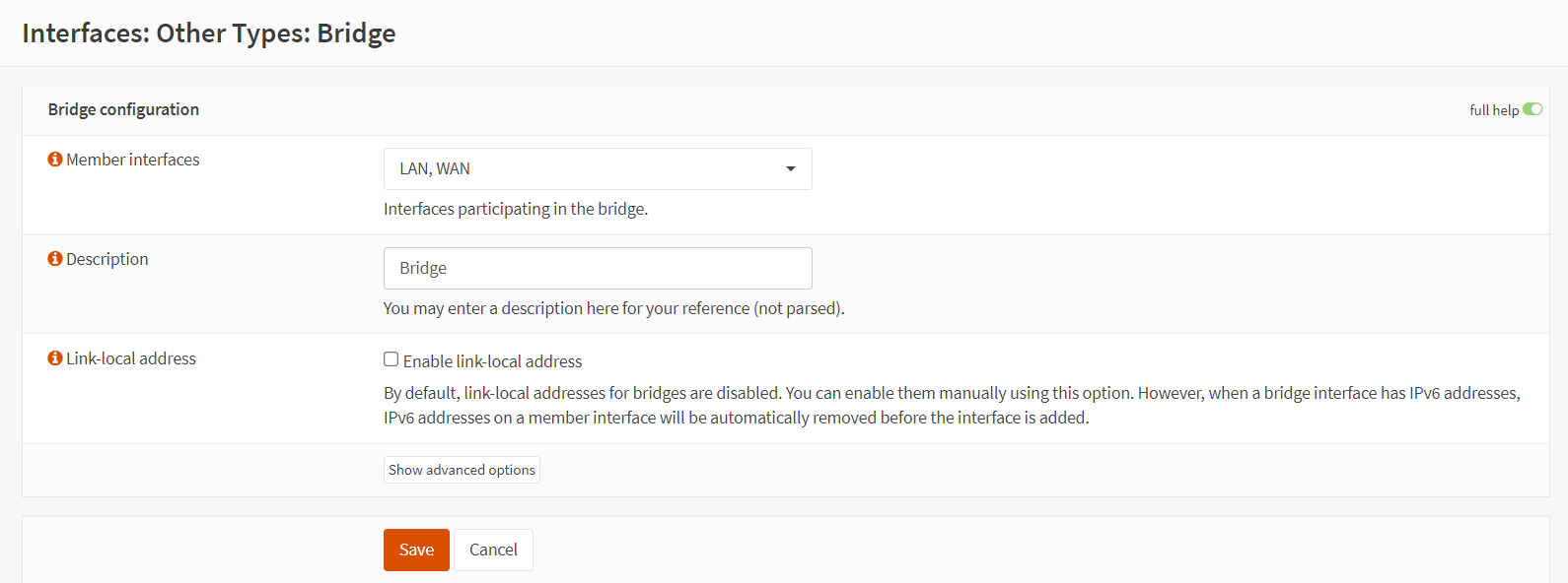
Figure 9. Saving new bridge interface settings
-
You may leave other options as default and click Save to add the bridge interface. The you should see newly created bridge interface,
bridge0, on the Bridge Interfaces page as given below.Figure 10. Viewing the bridge interfaces
4. Interface Assignment
To be able to configure and manage the filtering bridge (OPNsense) afterwards, we will need to assign a new interface to the bridge and setup an IP address. You may follow the steps given below for the interface assignment:
-
Navigate to Interfaces → Assignments on OPNsense UI
-
Type a descriptive name like
Bridgefor the newly createdBridge0network port and click on the+Add button.
Figure 11. Interface assignment for the bridge network port
-
You should see the interfaces assignments as given the below figure. To enable the
bridgeinterface and set IP configuration click on theBridge.
Figure 12. Editing bridge interface
-
Select the Enable Interface option in the
Basic Configurationpane to enable the bridge interface.Figure 13. Enabling bridge interface
-
You may select
Static IPv4or DHCP in the IPv4 Configuration Type option
Figure 14. Selecting IPv4 Configuration Type as Static IPv4
-
If you select Static IPv4 option, you must set IPv4 address and subnet mask in the Static IPv4 configuration pane. You may add new gateway by selecting Default gateway option and typing IP address in the Gateway IPv4 field depending on your WAN configuration.
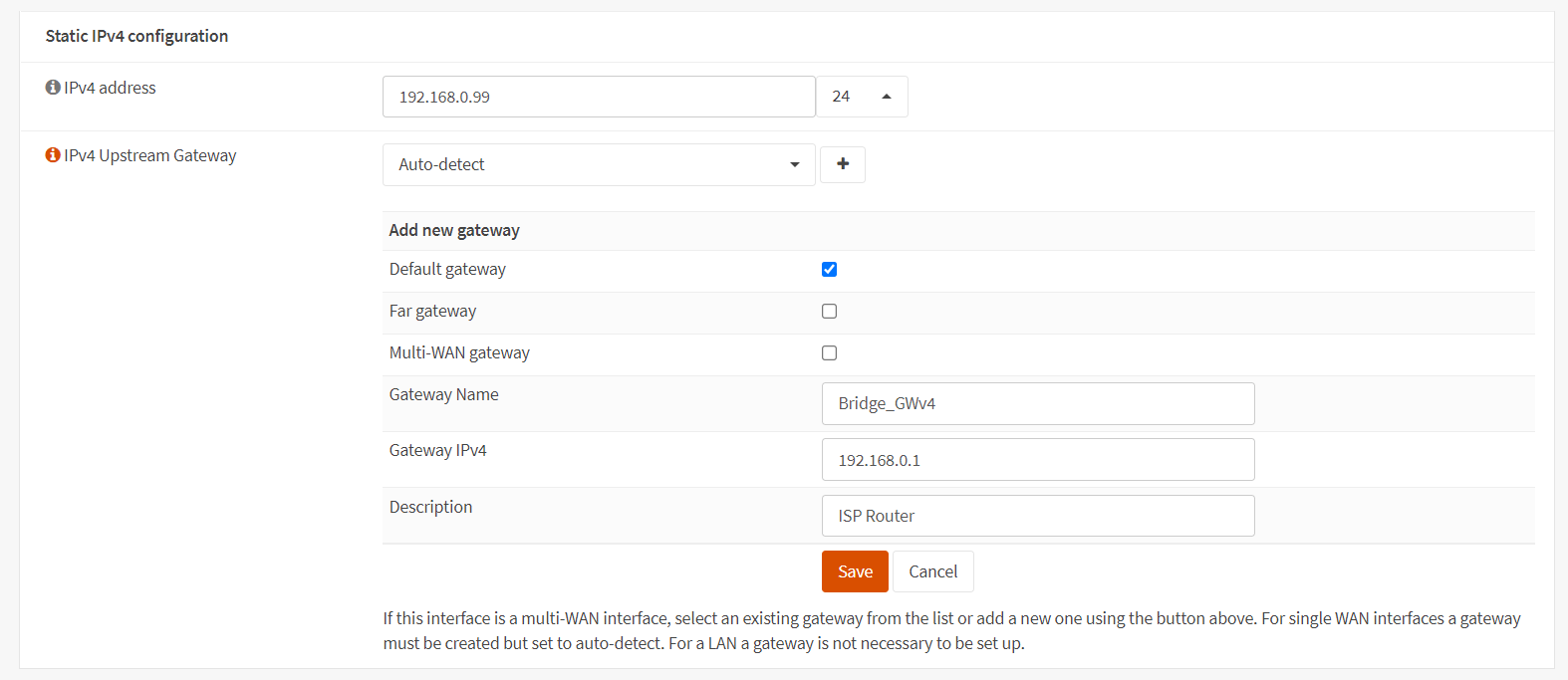
Figure 15. Setting IPv4 Configuration
-
Click Save to save the bridge interface configuration.
-
Click Apply Changes to activate the settings.

Figure 16. Applying Bridge Configuration
5. Disable Block Private & Bogon Networks
On the WAN interface, we must deactivate the blocking of private and bogon networks. To enable private network and bogon network traffic, you may follow the next steps given below:
-
Navigate to Interfaces → WAN on OPNsense UI.
-
Unselect Block private networks and Block bogon networks options in the
Generic Configurationpane.
Figure 17. Enable private network and bogon network traffic on WAN interface
6. Disable the DHCP Server on LAN
To disable the DHCP server on LAN you may follows the steps given below:
-
Navigate to Services → DHCPv4 → [LAN] on OPNsense UI.
-
Unselect Enable DHCP server on LAN interface.
Figure 18. Disabling DHCP server on LAN interface
7. Firewall Rule Configuration To Allow All Traffic
This step ensures that the bridge is completely transparent, with no filtering occurring. After verifying the bridge's functionality, you may put up the appropriate rules.
To add a rule per interface for allowing all traffic of any type, you may follow the next steps:
1.Go to Firewall → Rules on OPNsense UI.
-
Select Bridge interface and click
+Add button to add a rule.
Figure 19. Adding Firewall Rule on Bridge interface
-
Select
Passfor Action option. -
Select
infor Direction option. -
Select
anyfor Protocol option. -
Select
anyfor Source option.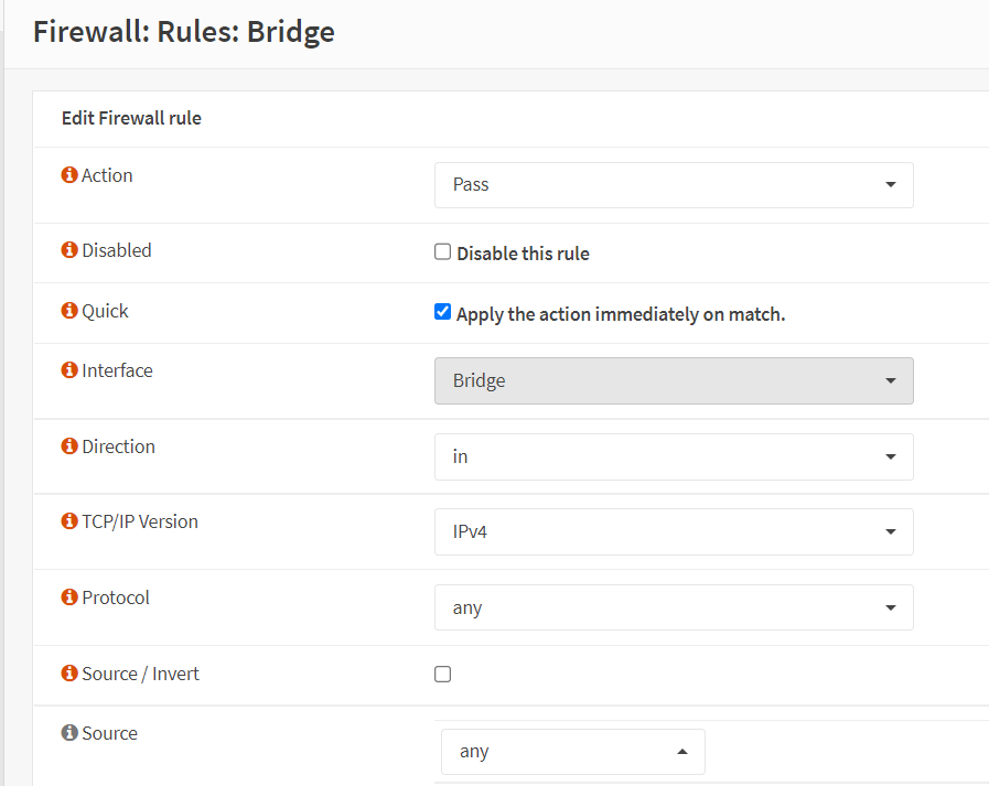
Figure 20. Creating Firewall Rule on Bridge interface to Allow All Incoming Traffic-1
-
Select
anyfor Destination option. -
Enable
Log packets that are handled by this rulefor Log option. -
Type
Allow Allfor Description option.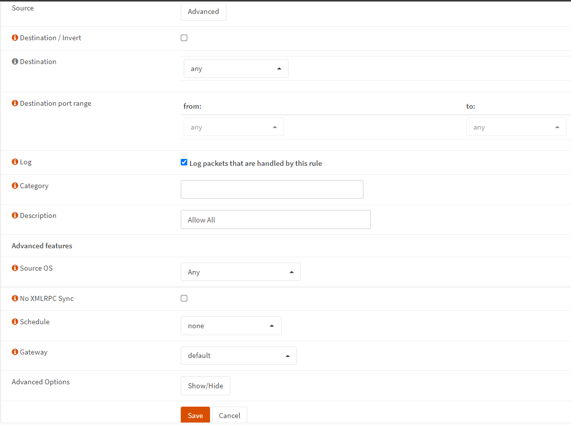
Figure 21. Creating Firewall Rule on Bridge interface to Allow All Incoming Traffic-2
-
Click Save and then click Apply Changes to activate the configuration.
-
Define a firewall rule on LAN interface as explained in steps 7.2-7.9.
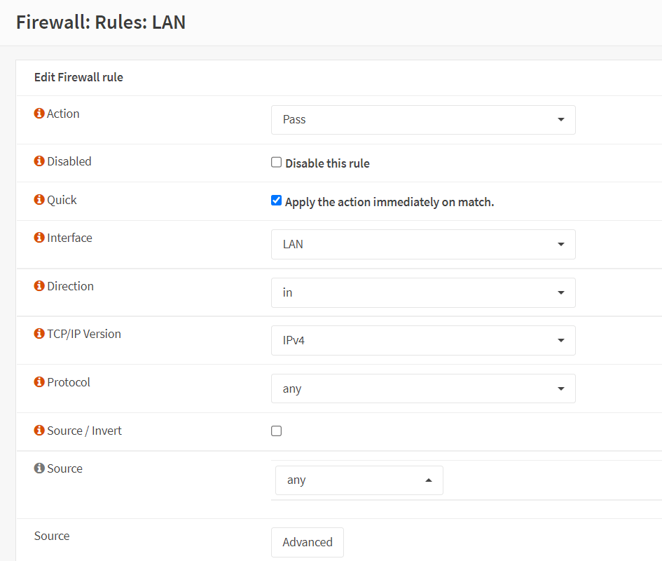
Figure 22. Creating Firewall Rule on LAN interface to Allow All Incoming Traffic
-
Define a firewall rule on WAN interface as explained in steps 7.2-7.9.

Figure 23. Creating Firewall Rule on WAN interface to Allow All Incoming Traffic
8. Disable Default Anti Lockout Rule
After configuring the bridge, member interface (WAN/LAN) rules will be disregarded. Therefore, you may skip this step. As each interface now has permit rules in place, we can safely remove the Anti-Lockout rule from the LAN by following next steps.
-
Navigate to Firewall → Settings → Advanced on OPNsense UI.
-
Unselect Disable anti-lockout option.

Figure 24. Disable anti-lockout rule
9. Set LAN and WAN Interface IPv4 Configuration to none
To remove the IP address in use for LAN and WAN, you may follows next steps:
-
Go to Interfaces → [LAN] on OPNsense UI.
-
Select
Nonefor the IPv4 Configuration Type. -
Click Save.
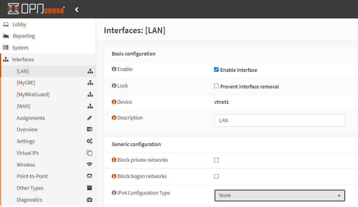
Figure 25. Setting IPv4 Configuration Type to None for LAN
-
Go to Interfaces → [WAN] on OPNsense UI.
-
Select
Nonefor the IPv4 Configuration Type. -
Click Save.

Figure 26. Setting IPv4 Configuration Type to None for WAN
-
Click Apply Changes to activate the configuration.
10. Adding Firewall Rules
Now, you have filtering bridge and can configure your firewall rules on bridge interface.
Rules on member interfaces of the bridge are disregarded.You should define filtering rules on the newly created bridge interface, Bridge0.
