pfSense Software Network Address Translation Guide
Network address translation (NAT) is the mapping of one Internet Protocol (IP) address to another by altering the header of IP packets as they traverse a router. As part of this strategy, NAT settings reveal just a single IP address for an entire network to the outside world, essentially disguising and enhancing the security of the whole internal network. Network address translation is often used in remote-access contexts because it conserves addresses while simultaneously enhancing security. This increases security while decreasing the number of IP addresses an organization needs.
NAT is a way for isolating external and internal networks (WANs and LANs) and sharing an external IP address among clients on the inside network. NAT is compatible with both IPv4 and IPv6 networks. IPv6 likewise supports Network Prefix Translation.
The majority of the options below make use of three separate addresses:
-
Source address
-
Destination address
-
Redirect address.
| Address | Description |
|---|---|
| Source | From where the traffic is coming. This is frequently left on "any". |
| Destination | Where the traffic is going. This is typically your external IP address for incoming traffic from the outside world. |
| Redirect | Where traffic should be rerouted. |
Disabling pf disables NAT on pfSense.
These addresses are used for the following purposes:
-
BINAT: NAT normally functions in one way alone. You may utilize bidirectional BINAT if both networks are of identical size. This might simplify your configuration. You can only use standard NAT if the sizes of your networks differ.
-
NAT Reflection: When a user on the internal network tries to connect to a local server by using the external IP address instead of the internal one, NAT reflection rewrites the request to use the internal IP address, so avoiding a detour and following rules meant for true outside traffic.
-
Pool Options: When numerous IPs are available, this option enables you to pick which IP is used. The default, Round Robin, distributes packets to each server sequentially. This option has no impact if just one external IP address is configured.
In its most prevalent use, Network Address Translation (NAT) enables many IPv4-using computers to connect to the Internet using a single IPv4 public address. The pfSense® software allows these basic installations as well as considerably more complicated NAT setups necessary in networks with numerous public IP addresses.
NAT is set in both the incoming and outbound directions. Outbound NAT describes the translation of traffic leaving a local network for a distant network, such as the Internet. Inbound NAT refers to distant network traffic entering a local network. The most used kind of incoming NAT is port forwarding, which is the sort of which the majority of administrators are most aware.
What is the Default NAT Configuration on pfSense?
This section details the pfSense software's default NAT settings. Automatically create the optimal NAT configuration that can be found. This setup may not be suited to certain circumstances, and pfSense software allows for its complete modification through the web interface. This is in contrast to the majority of other open-source firewall deployments, which do not include the characteristics frequently needed for networks that are not tiny and basic.
What is Default Outbound NAT Setup?
In a typical two-interface configuration consisting of a LAN and WAN, the default NAT configuration transforms Internet-bound traffic to the WAN IP address. When several WAN interfaces are installed, all outgoing traffic is automatically translated to the address of the active WAN interface.
IKE automatically configures a static port.
pfSense software detects WAN-type interfaces for use with NAT by looking for a gateway configured on the interface configuration if it has a static IP address, or by assuming the interface is a WAN if it is a dynamic kind such as PPPoE or DHCP.
What is Default Inbound NAT Setup?
By default, no Internet access is permitted on the WAN interface. If Internet-originating traffic must be let to reach an internal host, port forwarding or 1:1 NAT is necessary.
What is Port Forwarding?
Port forwarding enables access to a particular port, port range, or protocol on an internally-addressed network device. It was renamed from the more technically accurate "Inbound NAT" to make it more user-friendly. The word "port forward" was selected since it is what most people recognize in this context. This capability is referred to in other systems as "Destination NAT". Nevertheless, "Port Forward" is a misnomer, since port forward rules redirect complete protocols such as GRE or ESP in addition to TCP and UDP ports, and it is used for other forms of traffic redirection in addition to typical port forwarding. This is often used when hosting servers or using apps that need incoming Internet connections.
What are the Security Risks of Port Forwarding?
With its default setup, pfSense® software does not permit any Internet-originating traffic. This protects against anybody monitoring the Internet for vulnerable systems to attack. When a port forward rule is present, the firewall will permit any traffic that matches the applicable firewall rules. The firewall cannot distinguish between packets with malicious payloads and those with benign payloads. If the connection conforms to the firewall rule, it is permitted. The target system must utilize host-based controls to secure any services permitted via the firewall. Deploying an ID/IPS solution, like Snort or Suricata, and a next-generation firewall extension, such as Zenarmor, are other network protection mechanisms for eliminating the cybersecurity of port forwarding.
What is the Relationship Between Port Forwarding and Local Services?
Port forwarding takes priority over locally-running services, such as the web interface and SSH, on the firewall. If remote web interface access is permitted from the WAN through HTTPS on TCP port 443, for example, a port forward on the WAN for TCP port 443 will take priority and the web interface will no longer be available from the WAN. This has no effect on other interfaces; only the interface containing the port forward is affected.
What is the Relationship Between Port Forwarding and 1:1 NAT?
Port forwarding has priority over 1:1 NAT. If a port forward is set on an external IP address sending a port to a host and a 1:1 NAT entry is defined on the same external IP address forwarding everything to a different host, the port forward stays active and continues forwarding to the original host.
What are the Port Forwarding Settings on pfSense?
The following options are available when creating or modifying a port forward entry on pfSense software firewall:
-
Disable: Optional checkbox to Disable this NAT port forward. To disable the rule, choose this checkbox.
-
No RDR (NOT): Negates the meaning of this port forward, indicating that no redirection should be done if this rule is met. The majority of setups won't need this field. This would be used to override a forwarding action, which may be required in some circumstances to enable access to a service on the firewall using an IP address used for 1:1 NAT or for another sophisticated situation.
-
Interface: The interface on which port forwarding will be enabled. This will often be WAN. For extra WAN connections or local redirection, this interface may be changed. The interface is the point at which traffic for this port forward enters the firewall.
-
Address Family: IPv4 or IPv6 address family for the IP address on which this port will be routed. When an interface has addresses of both families, the address of the relevant family will be utilized. In addition, when choosing an interface, its address must correspond to this kind. When picking a certain IP address, the address family must match.
-
Protocol: Protocol to match with incoming traffic. This value must correspond to the kind of service being sent, whether TCP, UDP, or another option. The TCP/UDP option simultaneously forwards TCP and UDP using a single rule.
-
Source: By default, these choices are concealed behind an Advanced button and set to any source. The Source choices limit the IP addresses and ports from which this port forward may be accessed. They are often unnecessary. If the forwarded port must be accessible from any Internet location, the source must be
any. Use an alias for services with restricted access so that only a limited group of IP addresses may access the port forward. TheSource Port Rangemust be left asanyunless the service needs a specified source port since the vast majority of customers will utilize random source ports. -
Destination: The IP address of the source of the traffic that will be routed. In the majority of WAN port forwarding situations, this is the WAN Address. It may be a Virtual IP (see Virtual IP Addresses) over the WAN if numerous public IP addresses are available. If the
Invert Matchcheckbox is selected, the port forward will match any packet that does not match the destination. -
Destination port range: The initial destination port of the traffic before it is redirected to the specified target host. For forwarding a single port, insert the port in the
Frombox and leave theTobox empty. With this group's drop-down menus, a range of standard services is available for selection. Moreover, port aliases may be used to route a group of services. If an alias is provided here, the same alias must be used as theRedirect target port. -
Redirect target IP: The IP address to which traffic will be forwarded or diverted. IPv6 targets must have the same scope as their respective destinations.
tipWhen using an alias as a value for this field, only one IP address should be included. Utilizing numerous addresses will result in round-robin redirection of traffic to the target sites, although it is not optimal for this operation. If one of the target hosts is unavailable, traffic will still be routed to the unavailable site.
Use the HAProxy package for situations needing forwarding to several hosts, such as load balancing or failover scenarios.
-
Redirect target port: The beginning of the forwarded port range. If a range of ports, such as
19000-19100, is forwarded, only the local beginning point is supplied, since the number of ports must correspond one-to-one. This parameter permits opening a port on the outside that is distinct from the one the host on the inside is listening on. For example, for HTTP on an internal server, external port8888may forward to local port80. Through the drop-down menu, you may choose from a list of common services. Moreover, port aliases may be used to route a group of services. If an alias is used in this field, it must be used in theDestination port rangefield. -
Description: This field might include a brief description of the port forward's purpose or function.
-
No XML-RPC Sync: This option is only applicable if a HA Cluster setup is in use; otherwise, it should be omitted. Checking this option while using a HA cluster with configuration synchronization prevents the rule from being synchronized to the other cluster members. Generally, though, all rules should be synchronized. This option only prevents a rule from being overwritten on master nodes; it has no impact on slave nodes.
-
NAT Reflection: This option enables per-rule reflection to be enabled or disabled, overriding the global default.
-
Filter Rule Association: A port forward entry simply specifies the kind of traffic that will be diverted; a firewall rule is needed to allow any traffic to flow through the redirection.
Add associated filter ruleis chosen by default. The options offered are as follows:None: If this option is selected, no firewall rule is produced.Add associated filter rule: This option associates a firewall rule with this NAT port forward rule. Modifications made to the NAT rule are immediately reflected in the firewall rule. If this option is selected, a link to the corresponding firewall rule is posted here when the rule is saved. This is the optimal default behavior for the majority of usage situations.Add unassociated filter rule: This option generates a distinct firewall rule from the NAT port forward. NAT rule modifications must be manually reflected in the firewall rule. This is helpful if additional options or limits must be placed on the firewall rule as opposed to the NAT rule.Pass: This option utilizes a specificpfkeyword on the NAT port forward rule to flow through traffic without requiring a firewall rule. Due to the lack of a distinct firewall rule, any traffic matching this rule is sent to the target system.
Pass rules only function on the interface hosting the firewall's default gateway; they are incompatible with Multi-WAN.
How to Add Port Forward?
Port Forwards are handled through the Port Forward tab in Firewall > NAT. NAT rules are administered in the same way as pfSense firewall rules.
To add a forward port entry on your pfSense software, you may follow the following steps:
-
Navigate to Firewall > NAT > Port Forward on pfSense web UI.
-
Click the Add button with a UP icon to access the Port Forward editing panel.
-
Specify the port forwarding parameters as indicated in the previous Port Forwarding Settings section.

Figure 1. Adding Port Forwarding for HTTP-1
- Click Save.
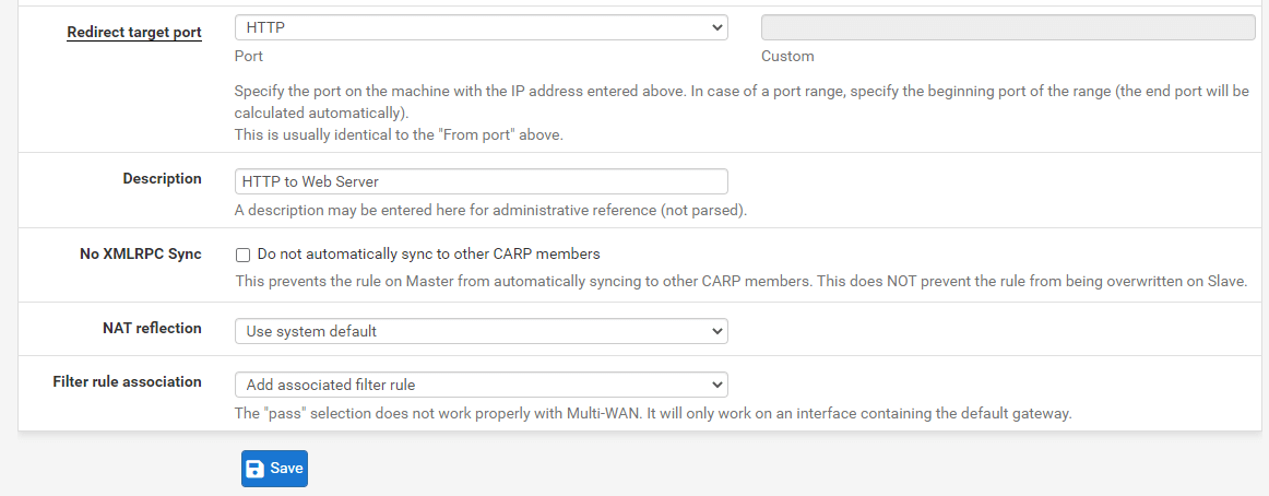
Figure 2. Adding Port Forwarding for HTTP-2
- Click the Apply Changes button to activate the settings.
The following figure illustrates an example of the port forward editing page with the correct settings to route HTTP (port 80) packets intended for the WAN IP address to the internal system at 10.1.1.15.
After selecting Save, the port forward list is presented again, as shown in the next Figure, with the newly generated item visible.
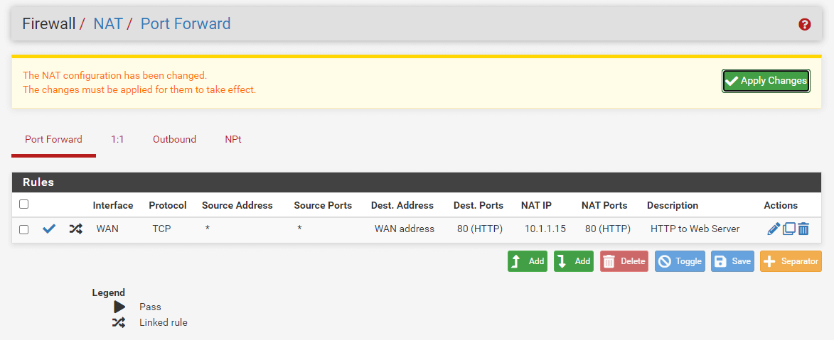
Figure 3. Viewing NAT Port Forward Ruleset
Under Firewall > Rules on the tab for the interface on which the port forward was established, double-check the firewall rule. As illustrated in Figure Port Forward Firewall Rule, the rule indicates that traffic is permitted to enter the internal IP address on the specified port.
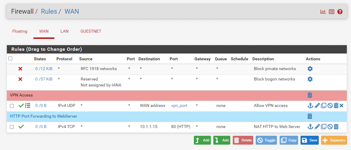
Figure 4. HTTP Port Forwarding Firewall Rule on WAN Interface
If feasible, the Source of the automatically created rule should be limited. This is impractical for things such as mail and web servers that must be widely accessible, but for remote management services such as SSH, RDP, and others, only a limited number of hosts should be allowed to connect to a server from the Internet using these protocols. Creating an alias of allowed hosts and then changing the source to the alias is a far more secure method. Otherwise, the server is accessible to everyone on the Internet. After ensuring that the port forward works with the unconstrained source, limit the source as required.
If everything seems to be in order, the port forward will function when checked from outside the network.
How to Monitor Changes to Port Forwards?
A timestamp is appended to a port forward item when it is created or last updated to indicate which user originated the rule and who most recently edited it.
Figure 5. Tracking NAT Port Forwarding Rule
Firewall rules established automatically by related NAT rules are likewise identified as such on the creation date of the linked firewall rule.
Figure 6. Tracking Firewall Rule for NAT Port Forwarding
What are Limitations of Port Forwarding?
For each accessible public IP address, a single port may only be routed to one internal host. For instance, if only one public IP address is available, only one internal web server using TCP port 80 may be set up to handle web traffic. Additional servers must use other ports, such as 8080. Using five accessible public IP addresses as Virtual IP addresses enables the configuration of five internal web servers utilizing port 80.
Port sharing may be performed for services such as HTTP and HTTPS utilizing the HAProxy software. A proxy may make more sophisticated judgments about how to transmit requests to internal hosts if requests can be differentiated in some manner, such as by distinct request hostnames.
There is a rare but sometimes relevant exception to this rule. If a specific port must be forwarded to a specific internal host only for certain source IP addresses, and the same port can be forwarded to a different host for other source IP addresses, the source address can be specified in the port forward entries.
NAT reflection must be enabled for port forwarding on WAN addresses to be accessible using their appropriate WAN IP address from internal-facing interfaces. Always test port forwarding from a machine with a separate Internet connection, and never from inside the network. Checking external connections from a mobile device via 3G/4G is a fast and straightforward method.
Service Self-Configuration With UPnP or NAT-PMP
Several applications enable Universal Plug-and-Play (UPnP) or NAT Port Mapping Protocol (NAT-PMP) to establish NAT port forwarding and firewall rules automatically. There are even greater security issues, although the advantages of residential usage often exceed the risks.
Traffic Redirection Using Port Forwards
Port forwarding may be used to transparently reroute traffic from an internal network. Port forwarding that specifies the LAN or another internal interface reroutes traffic to the chosen destination. This is often used for transparently proxying HTTP traffic to a proxy server or diverting all outbound DNS traffic to a single server.
What is 1:1 (One-to-One) NAT?
1:1 NAT (pronounced "one-to-one NAT") translates an external (often public) IP address to an internal IP address (usually private).
Overriding the Outbound NAT setup, the 1:1 NAT entry maps all traffic originating from the private IP address to the public IP address specified in the entry.
All Internet traffic intended for the public IP address indicated in the mapping is converted to the private IP address and then analyzed against the firewall ruleset on the incoming WAN interface. If the firewall rules enable traffic to a target with a private IP address, it is forwarded to the internal host.
1:1 NAT translates whole subnets in addition to individual addresses, assuming that the subnets are the same size and correspond with the subnet borders.
1:1 NAT preserves the ports on a connection; for outbound connections, the source ports used by the local system are maintained, similar to the behavior of Static Port on outbound NAT rules.
What are the Risks of 1:1 NAT?
If WAN firewall rules enable traffic, the hazards posed by 1:1 NAT are comparable to port forwarding. Whenever regulations let traffic, potentially hazardous traffic may enter a local network. There is a modest increase in risk when using 1:1 NAT since firewall rule errors might have more severe repercussions. Using port forward entries, traffic is restricted by NAT rule and firewall rule limitations. If TCP port 80 is opened via a port forwarding rule, an allow all rule on the WAN would only permit TCP port 80 on the internal host. If 1:1 NAT rules are in place and an allow-all rule exists on the WAN, the whole internal host will be accessible from the Internet if both rules are in place. Despite the fact that misconfigurations are always a risk, this is often not a cause to avoid 1:1 NAT. Keep this in mind while establishing firewall rules, and never allow anything that isn't necessary.
What are 1:1 NAT Rule Options?
When creating or updating a 1:1 NAT rule entry under Firewall > NAT on the 1:1 tab, the following options are available for each entry:
-
Disabled: Controls whether or not the 1:1 NAT entry is activated.
-
Not BINAT (NOT): This option, when enabled, prevents traffic matching this 1:1 rule from being subject to 1:1 NAT if it would otherwise match a rule below it in the ruleset.
-
Interface: Interface where 1:1 NAT translation will occur, often a WAN link. The 1:1 NAT rule only impacts traffic entering and leaving this interface. If numerous WAN-type interfaces exist, directing traffic to utilize this interface requires static routing, policy routing, or comparable setups.
-
Address Family: Choose IPv4 or IPv6 depending on the kind of address that is used in the fields of this rule.
tipWhilst 1:1 NAT rules may be used with IPv6, IPv6 Network Prefix Translation (NPt) is more suitable for translating the prefix of IPv6 traffic in the majority of scenarios.
-
External subnet IP: The IP address to which Internal IP addresses will be converted when entering or exiting the Interface. Often, this is a Virtual IP address on Interface or an IP address that is forwarded to the firewall through Interface.
-
Internal IP: The IP address behind the firewall that is converted to the IP address of the External subnet. Often, this is an IP address behind the firewall. The device with this IP must directly (connected) or indirectly utilize this firewall as its gateway (via static route). Specifying a subnet mask in this field will translate the whole of the network that matches the subnet mask. Using
x.x.x.0/24, for instance, converts any subnet address to its counterpart in the external network. -
Destination: Optional, a network limitation that restricts 1:1 NAT entries. When a value is present, the 1:1 NAT only takes effect when traffic is traveling from the Internal IP address to the Destination address on the way out, or from the Destination to the External subnet IP address on the way in. The Destination field is compatible with aliases.
-
Description: A textual explanation of the entry's purpose that is optional.
-
NAT reflection: A replacement for the global NAT reflection settings. Use system default respects the global NAT reflection settings, enable always performs NAT reflection for this entry, and disable never performs NAT reflection for this item.
How to Configure a 1:1 NAT rule?
You may configure 1:1 NAT rule on your pfSense firewall by following the next steps:
- Navigate to Firewall > Virtual IPs on pfSense web UI to add a Virtual IP for the public IP address to be used for the 1:1 NAT entry.
Figure 7. Firewall Virtual IP Addresses
-
Click the +Add button to add a new virtual IP Address.
-
Select the
Proxy ARPas the Type. -
Select
WANas the Interface. -
Select
Single addressas the Address Type. -
Specify your external public IP address in Address(es) field.
-
Add a Description, such as
My Public IP address.
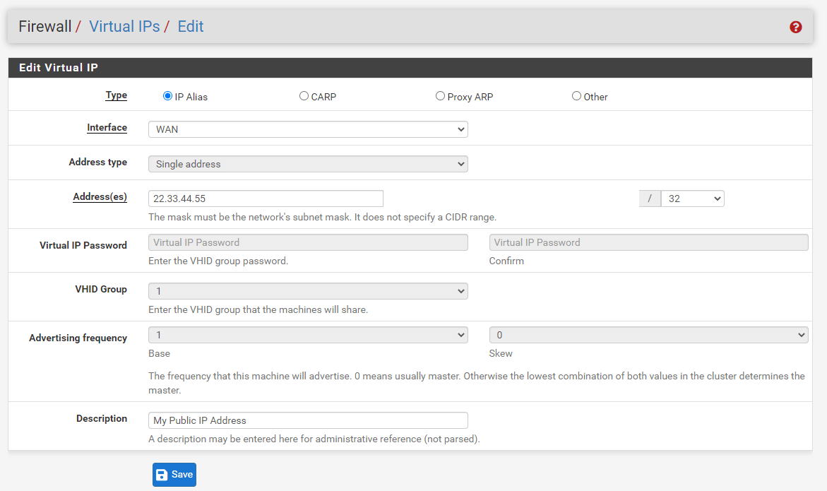
Figure 8. Adding Firewall Virtual IP Addresses
-
Click Save to save the changes.
-
Click Apply changes to activate the settings.
-
Navigate to Firewall > NAT > 1:1 tab.
-
Click Add button with a UP arrow icon to create a new 1:1 entry at the top of the list.
-
Configure the 1:1 NAT entry described in the
What are 1:1 NAT Rule Optionssection. -
Click Save.
-
Click Apply Changes to activate the settings.
Single IP Address 1:1 NAT Configuration Example
This section details the configuration of a 1:1 NAT entry with a single internal and exterior IP address. 22.33.44.55 is a Virtual IP Address on the WAN interface in this scenario. In the majority of installations, this will be replaced with a valid public IP address. The e-mail server associated with this mapping is located on a DMZ section with the internal IP address 10.1.1.25. The 1:1 NAT, also known as static NAT (SNAT), entry to translate IP address 22.33.44.55 to IP address 10.1.1.25. To define a single IP address 1:1 NAT rule, you may follow the next steps:
-
Navigate to Firewall > Virtual IPs on pfSense web UI to add a Virtual IP for the public IP address to be used for the 1:1 NAT entry.
-
Click the +Add button to add a new virtual IP Address.
-
Select the
Proxy ARPas the Type. -
Select
WANas the Interface. -
Select
Single addressas the Address Type -
Specify your external public IP address in Address(es) field, such as
22.33.44.55. -
Add a Description, such as
Email Server IP address. -
Click Save to save the changes.
-
Click Apply changes to activate the settings.
-
Navigate to Firewall > NAT > 1:1 tab.
-
Click Add button with a UP arrow icon to create a new 1:1 entry at the top of the list.
-
Select
Single Hostfrom the Type drop-down menu and specify Address, such as22.33.44.55for External subnet IP option. -
Select
Single Hostfrom the Type drop-down menu and specify Address/mask, such as10.1.1.25for Internal IP option. -
Fill in the Description field, such as
E-mail Server 1:1 NAT. -
You may leave other settings as default.
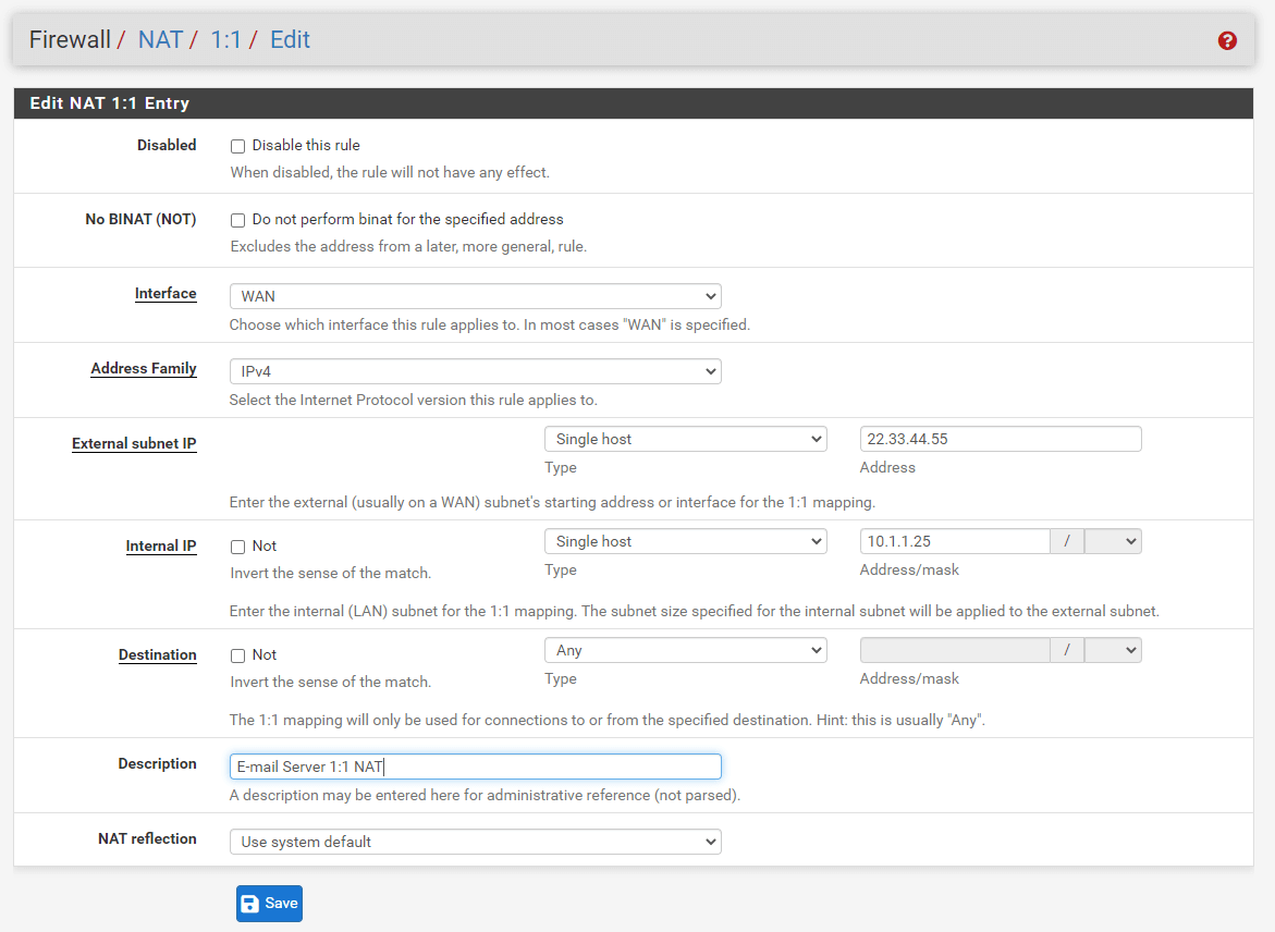
Figure 9. Adding Single IP address 1:1 NAT rule
-
Click Save.
-
Click Apply Changes to activate the settings.
IP Address Range 1:1 NAT Configuration Example
Using CIDR ranges, 1:1 NAT may be established for several public IP addresses. In this example, a /30 CIDR IP address range is setup using 1:1 NAT.
| External IP | Internal IP |
|---|---|
| 100.100.100.64/30 | 10.1.1.64/30 |
| 100.100.100.64 | 10.1.1.64 |
| 100.100.100.65 | 10.1.1.65 |
| 100.100.100.66 | 10.1.1.66 |
| 100.100.100.67 | 10.1.1.67 |
The last octet of the IP addresses need not be same on the inside and outside, although it is easier to understand if it is.
-
Navigate to Firewall > NAT > 1:1 tab.
-
Click Add button with a UP arrow icon to create a new 1:1 entry at the top of the list.
-
Select
Single Hostfrom the Type drop-down menu and specify Address, such as100.100.100.64for External subnet IP option. -
Select
Networkfrom the Type drop-down menu and specify Address/mask, such as10.1.1.64/30for Internal IP option. -
Fill in the Description field, such as
IP Range NAT. -
You may leave other settings as default.
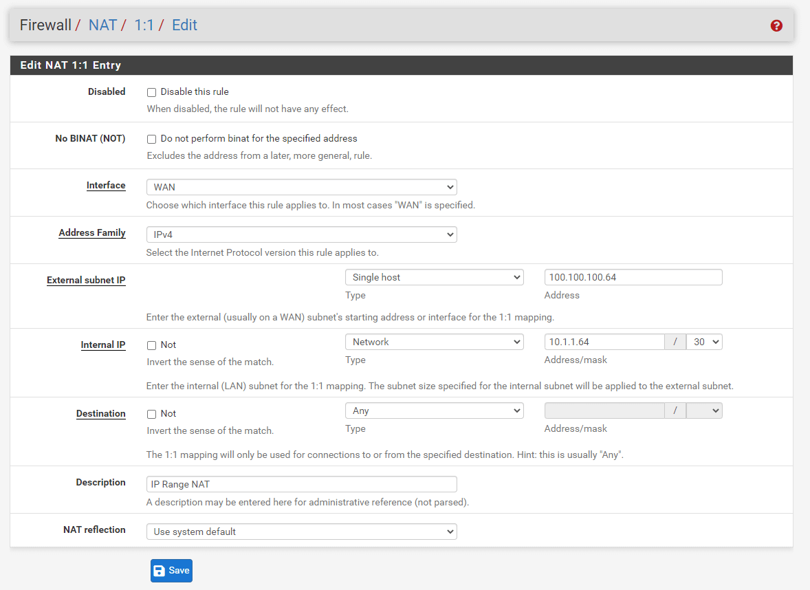
Figure 10. Adding IP address Range 1:1 NAT rule
-
Click Save.
-
Click Apply Changes to activate the settings.
How to Handle NAT and Firewall Requests?
Configuring NAT and firewall rules requires an understanding of the sequence in which firewalling and NAT occur. The following Figure - Ordering of NAT and Firewall Requests illustrates the fundamental logical order. The diagram also indicates where tcpdump fits in since its usage for troubleshooting is discussed under Packet Capture later in this guide.
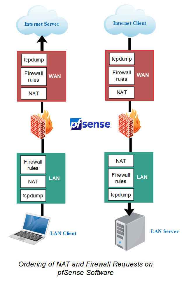
Figure 11. Ordering of NAT and Firewall Requests
In conventional settings, each tier is not necessarily traversed in both directions. Nevertheless, using floating rules, manual outbound NAT, or other complex configurations may traverse each layer in both directions. The illustration only includes basic incoming and outbound traffic situations.
Regarding the processing of the ruleset, the following is the order:
-
NAT outbound rules
-
Inbound NAT rules including Port Forwarding (including
rdr passand UPnP) -
Rules dynamically received from RADIUS for IPsec and OpenVPN clients
-
Internal automatic rules (pass and block for various items like lockout, snort, DHCP, etc.)
-
User-defined rules:
- Rules specified on the floating tab
- Rules specified on interface group tabs (Including IPsec and OpenVPN)
- Rules specified on interface tabs (WAN, LAN, OPTx, etc)
-
Automated VPN rules
Example of Firewall/NAT Processing Order
The traffic from LAN to WAN is treated as outlined in the following example in further detail. If a rule type does not exist or does not match, it is skipped.
-
Port forwarding on the LAN interface or 1:1 NAT (e.g. proxy or DNS redirects)
-
Rules for the firewall's LAN interface:
- Inbound floating rules on LAN
- Rules for interface groups that include the LAN interface
- LAN tab rules
-
1:1 NAT or Outbound NAT rules on WAN
-
Floating rules that match outbound on WAN
Port forwarding on WAN and WAN tab firewall rules do not apply in this scenario.
For WAN-initiated traffic, the sequence is same, but the direction is reversed:
-
Port forwarding on the WAN interface or 1:1 NAT (e.g. public services)
-
Rules for the WAN interface's firewall:
- Inbound floating rules on WAN
- Rules for interface groups that include the WAN interface
- WAN tab rules
-
1:1 NAT or Outbound NAT Rules on LAN
-
Floating rules that match outbound on LAN
Depending on the direction of the traffic, tcpdump is always the first and final program to view it. First, on the incoming interface prior to any NAT or firewall processing, then on the outgoing interface. It reveals the contents of the wire.
Floating rules without quick set process as “last match wins” instead of “first match wins”. method. If a floating rule is established without quick and a packet matches that rule as well as a later rule, the later rule will be applied. This is reverse of the other tab rules (groups, interfaces) and quick set rules, which cease processing once a match is made.
Using Extrapolation to Extra Interfaces
The above picture and lists only depict a simple LAN and WAN implementation with two interfaces. The same requirements apply when using extra interfaces. The behavior of communication between two internal interfaces is identical to that of LAN-to-WAN traffic; however, the default NAT rules do not translate traffic between internal interfaces, hence the NAT layer is inactive in these instances. If there are Outbound NAT rules that match traffic between internal interfaces, they will be applied as indicated.
Rules for NAT
On the way into an interface, NAT is applied prior to firewall rules, therefore if the destination is translated on the way in (e.g. port forwarding or 1:1 NAT on WAN), the firewall rules must match the translated destination. In the normal situation of a port forward on the WAN, this implies that the rule must match the private IP address of the target on the LAN.
Outbound NAT applies before firewall rules on the way out of an interface, therefore any floating rules matching outbound on an interface must match the source after it has been translated by outbound NAT or 1:1 NAT.
What is NAT Reflection?
NAT reflection is the capability to access external services from an internal network using the external (often public) IP address, as if the client were on the Internet. Although many commercial and open-source firewalls do not offer this capability at all, pfSense® software provides robust support for NAT reflection; nonetheless, certain environments will need a split DNS infrastructure to allow this functionality.
When feasible, split DNS is the ideal method for accessing resources so that the firewall is not required to access internal services. This section concludes with a discussion of Split DNS.
How to Configure NAT Reflection?
To globally activate NAT Reflection on your pfSense firewall, you may follow the next steps:
-
Navigate to System > Advanced > Firewall & NAT on pfSense Web UI.
-
Scroll down to
Network Address Translationpane. -
Configure the following NAT Reflection options.
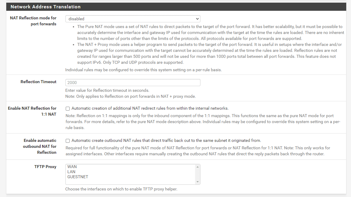
Figure 12. Configuring NAT Reflection
-
Click Save at the bottom of the page.
-
Click Apply Changes to activate the settings.
What are NAT Reflection Options?
The following options are available for the NAT reflection feature of pfSense software:
-
NAT Reflection Mode for Port Forwarding: There are three options available for NAT Reflection mode for port forwards:
Disable: NAT Reflection will not be done, however, per-rule reflection may be enabled.NAT + Proxy: Enables NAT Reflection by utilizing a proxy program to forward traffic to the destination port. This is helpful in configurations where the interface and/or gateway IP address used to communicate with the target cannot be known properly at the time the rules are loaded. Reflection rules for usage with the proxy are not established for ranges wider than 500 ports, and a total of 1000 ports will not be utilized across all port forwards. This mode only works with TCP and not UDP. As this is a proxy, the IP address of the firewall nearest to the server is the source address of the traffic as perceived by the server.Pure NAT: Allows NAT Reflection utilizing just NAT rules inpfto forward packets to the port forward's destination. At the moment the rules are loaded, it must be able to precisely establish the interface and gateway IP address used for communication with the target. Other than protocol limitations, there are no inherent constraints on the number of ports. All known protocols for port forwarding are supported. If servers and clients share the same subnet, theEnable automatic outbound NAT for Reflectionoption will disguise the source of the traffic so that it goes back through the firewall correctly.
-
Reflection Timeout: This option regulates how long the NAT proxy daemon will wait before ending a connection. It applies solely to NAT + Proxy mode. Provide a value in seconds.
-
Enable NAT Reflection for 1:1 NAT: Using the external IP address of a 1:1 NAT entry, clients on internal networks may connect to locally hosted services. Check both
Enable NAT Reflection for 1:1 NATandEnable automatic outbound NAT for Reflectionto completely enable the functionality. If clients and servers are on the same subnet, just the second option is essential. -
Activate automatic outbound NAT for Reflection: This option enables extra NAT rules for
1:1 NAT ReflectionandPure NATmode NAT Reflection for port forwarding when enabled. These extra rules obfuscate the client's originating address to ensure that reply traffic goes across the firewall. Without this, client-server communications would fail because the server will respond directly to the client using its internal IP address. The client will terminate the connection if it does not get a response from the public IP address.
What are NAT Reflection Restrictions?
NAT reflection is a hack because it routes unnecessary traffic through the firewall. Due to the restricted choices pf provides for handling certain cases, the pfSense NAT + Proxy reflection solution has some restrictions.
NAT reflection is not enabled for port ranges bigger than 500 in NAT + Proxy mode, therefore this mode is basically restricted to operating solely with TCP. If clients and servers are connected to the same interface of the firewall, the other modes need extra NAT to occur. This additional NAT conceals the client's source address, making the traffic seem to come from the firewall so that the connection may be formed.
The best method for supporting huge port ranges and 1:1 NAT is split DNS. Even commercial firewalls need the maintenance of a split DNS infrastructure, which is often not problematic.
What is Split DNS?
Using a separate DNS infrastructure is a preferred option for NAT reflection. Split DNS refers to a DNS setup in which, for a particular hostname, public Internet DNS resolves to the public IP address and internal network DNS resolves to the private, internal IP address. The manner of handling this will differ based on a company's DNS infrastructure, but the ultimate effect will be the same. Since hostnames correspond to private IP addresses inside the network, NAT reflection is unnecessary and clients may access servers directly.
Split DNS enables servers to see the genuine client IP address, and connections between servers and clients on the same subnet bypass the firewall.
The only situation in which split DNS does not function effectively is when the exterior and internal port numbers mismatch. Using split DNS, the port number must match both locations.
How to Configure DNS Resolver/Forwarder Overrides?
If pfSense is the DNS server for internal hosts, host overrides in the DNS Resolver or DNS forwarder may enable split DNS capabilities.
To add an override to the DNS Resolver, you may follow the next steps::
-
Navigate to the Services > DNS Resolver on pfSense web UI.
-
Scroll down to the ** Host Overrides ** pane.

Figure 13. Host Overrides
-
Click
+Addbutton Under to see the Host Override options page. -
Configure the host override as required using the server's internal IP address. See Host Overrides. The following figure demonstrates an override for
example.comandwww.example.com.
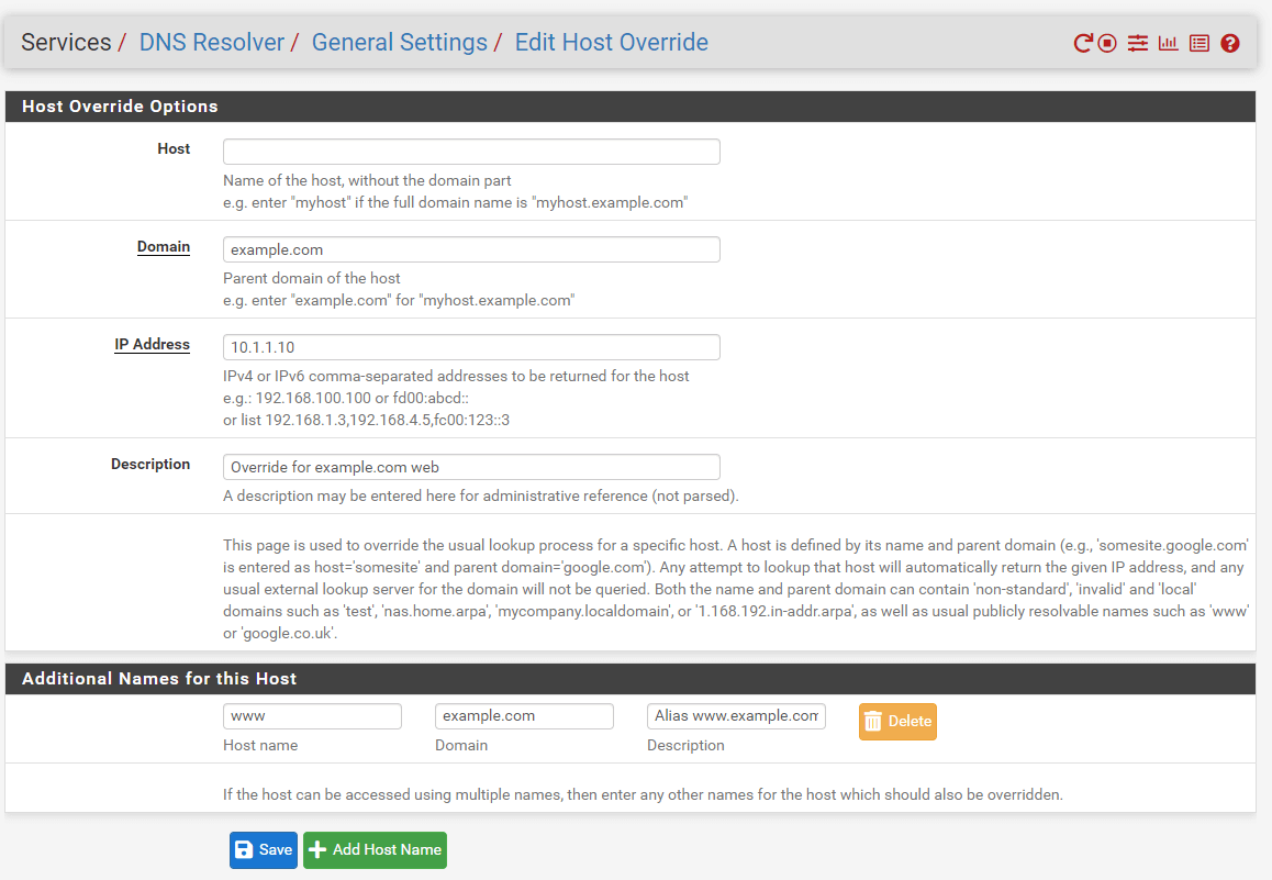
Figure 14. Adding Host Overrides
-
Click Save
-
Click the Apply Changes button.
In this respect, the DNS Forwarder functions similarly. If the DNS Forwarder rather than the DNS Resolver is enabled, put the overrides there.
Any hostname employed inside the firewall requires an override.
Private DNS servers
When utilizing a separate DNS server on an internal network, such as Microsoft Active Directory, the DNS server administrator must generate zones and other domain records for all domains hosted on the network (A, CNAME, MX, etc.).
In setups running the BIND DNS server where the public DNS and private DNS are housed on the same server, the views feature of BIND is used to resolve DNS differently for internal and external hosts. Other DNS servers may provide comparable features. See their documentation for details.
What is Outbound NAT?
Outbound NAT, also known as Source NAT, determines how pfSense® software translates the source address and ports of outgoing traffic. Go to Firewall > NAT > Outbound to set up Outbound NAT.
There are four different Outbound NAT Modes:
-
Automatic External NAT: The default option, executes NAT automatically from internal interfaces such as LAN to external interfaces such as WAN.
-
Hybrid Outbound NAT: Utilizes both manual and automated rules for traffic that does not match manually input rules. This option is the most versatile and simple to use for administrators who want a little amount of additional control but do not wish to manually manage the complete list.
-
Manual Outbound NAT: Respects just the manually specified rules, nothing else. Provides the greatest control but is difficult to administer, since any changes to internal interfaces or WANs must be manually accounted for in the rules. On moving from automatic to manual, if the list is empty, the list is filled with rules comparable to the automatically created set.
-
Disable Outbound NAT: Turns off all outbound NAT. Helpful if the firewall includes only routable addresses (public IP addresses, for instance) on all LANs and WANs.
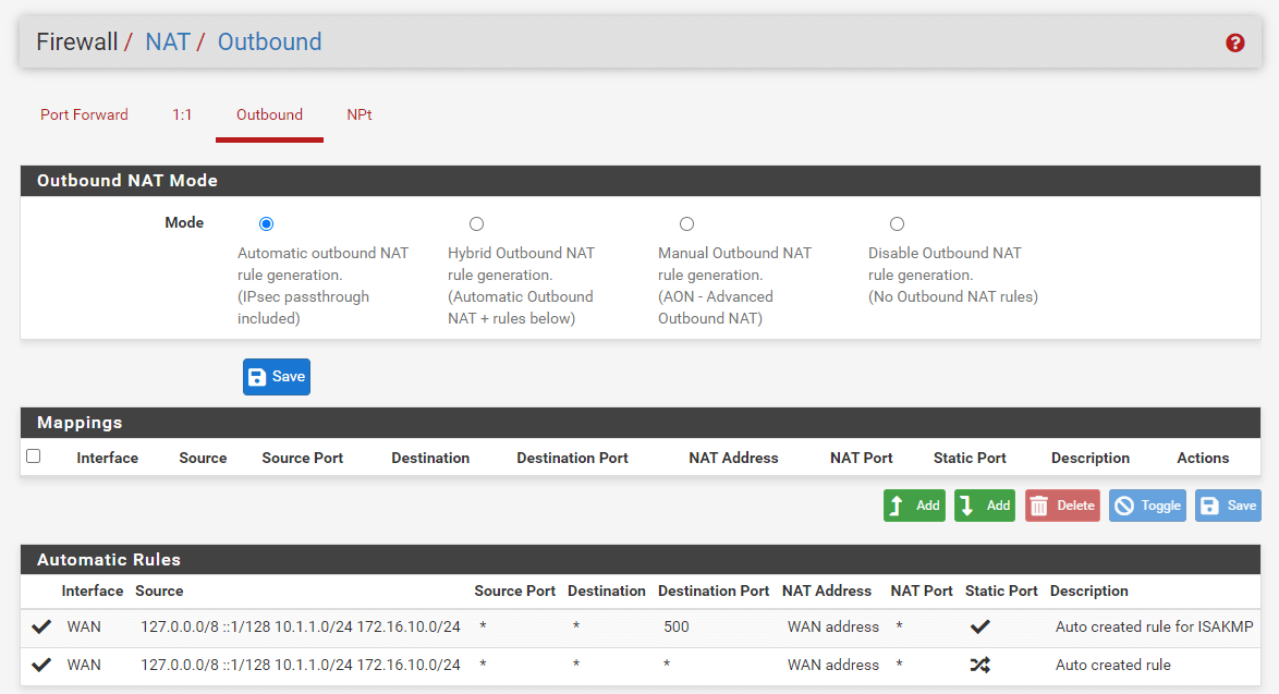
Figure 15. Outbound NAT Mode options on pfSense
Click the Save button after modifying the Mode value to save the new value.
On networks with a single public IP address per WAN, manual outbound NAT is often unnecessary. If manual control is required, the optimal option is hybrid. Manual outbound NAT provides greater granular control over all elements of translation in scenarios with numerous public IP addresses and complicated NAT needs.
It is crucial to NAT outgoing traffic to a CARP VIP address in situations using High Availability with CARP. This may be achieved in manual or hybrid mode.
Like with other rules in pfSense, outbound NAT rules are evaluated from the top of the list to the bottom, with the first match taking precedence. Even if there are rules on the Outbound NAT page, they will not be obeyed until the Mode is set to Hybrid Outbound NAT or Manual Outbound NAT.
Outbound NAT regulates solely the behavior of traffic leaving an interface. It does not control the interface via which the firewall's traffic will depart. This is handled by the routing table or policy routing (Policy routing).
What is Default Outbound NAT Rules?
When configured to the default Automatic Outbound NAT mode, pfSense maintains a set of NAT rules to convert traffic leaving any internal network to the IP address of the WAN interface which the traffic departs. Static route networks and remote access VPN networks are included in the automatic NAT rules.
When outbound NAT is set for Automatic or Hybrid modes, the automated rules are provided in the bottom area of the screen titled Automatic Rules.
If the Outbound NAT rule list is empty, switching to Manual Outbound NAT and saving will produce a complete set of rules similar to the automatic rules.
What is Static Port for Outbound NAT?
Except for UDP port 500(IKE for IPsec VPN traffic), the pfSense software rewrites the source port on all outbound connections by default. Certain operating systems perform source port randomization inadequately, if at all. This facilitates IP address spoofing and enables fingerprinting of computers inside the firewall based on their outward traffic. These possible (but improbable) security flaws are eliminated by rewriting the source port. Outbound NAT rules, including automated rules, that are configured to randomize the source port will display a randomize source port icon in the Static Port column.

Figure 16. Static Port on Automatic Outbound NAT rules
The randomization of source ports breaks certain uncommon applications. The default Automatic Outbound NAT policy removes source port randomization for UDP 500 since rewriting the source port would nearly always break it. Outbound NAT rules that maintain the original source port are referred to as Static Port rules and have a checkmark in the Static Port column. By default, the source port is rewritten for all other traffic.
When the source port is altered, other protocols, such as those used by gaming consoles, may no longer function correctly. To deactivate this feature, choose the Static Port option.
To add a rule for a device with static source port requirements, you may follow the next steps:
-
Navigate to Firewall > NAT > Outbound tab on pfSense web UI.
-
Select Hybrid Outbound NAT Rule Generation.
-
Click Save.
-
Click Add button with a UP arrow icon to put a new NAT rule to the top of the list. Set the rule to match traffic that needs a static port, such as a PBX or gaming console's source address.
-
Select
WANfor the Interface option. -
Set Protocol to
any. -
Set Source to
Networkand enter the IP address of your device, and the following subnet mask field to/32, -
Set Destination to
anyand leave the other fields as they are.

Figure 17. Advanced Outbound NAT Entry Configuration
-
Select
Interface Addressfor Address to map the Connections matching this rule to the Interface Address. -
Check
Static Portso that the pfSense NAT does not use a different port number, -
Type a Description.
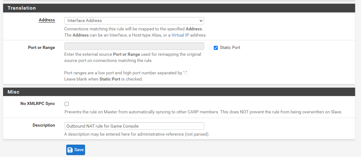
Figure 18. Outbound NAT Rule Configuration for Game Console
-
Click Save.
-
Click the Apply Changes button.
With this modification, the source port of outbound traffic matching the rule will be maintained. Whenever two local hosts utilize the same source port to communicate with the same remote server and port using the same external IP address, it is recommended practice to use rigorous constraints while employing a static port to prevent any possible conflict.
How to Disable Outbound NAT?
Disable NAT for the routable subnet if public IP addresses are used on local interfaces and NAT is not needed to transit traffic across the firewall. This is accomplished in a number of ways:
- Set the outbound NAT mode to
Disable Outbound NAT rule generation. (No Outbound NAT rules)if NAT is not needed for any interface.

Figure 19. Disabling Outbound NAT Rule Generation
- Using Hybrid Outbound NAT, a rule specified with Do not NAT deactivates NAT for matched traffic.
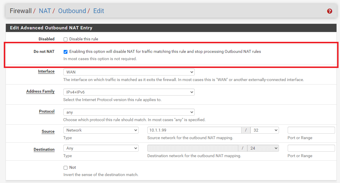
Figure 20. Disabling Outbound NAT Rule on Hybrid Outbound NAT
- Using Manual Outbound NAT, Delete (or do not generate) any NAT rules matching the routable subnets.
In any of the aforementioned situations, outbound NAT will no longer be active for the specified source IP addresses, and pfSense will route public IP addresses without translation.
How to Configure Manual Outbound NAT Rule?
Outbound NAT rules are very adaptable and capable of translating traffic in a variety of ways.
The NAT rules are displayed on a single page and the Interface column is a source of confusion for some: Once traffic leaves an interface, only the outbound NAT rules configured for that interface are reviewed.
On the Firewall > NAT > Outbound page, click Add button with a UP arrow icon to add a rule to the top of the list. Click Add button with a Down arrow icon to add a rule at the bottom of the list. Put explicit rules at the top, followed by more general ones. The firewall processes the rules from the top of the list to the bottom, applying the first rule that matches. Rules may be reordered in accordance with one's preferences.
Available Outbound NAT rule options are as follows:
-
Disabled: Toggles whether this rule is active or inactive.
-
Do not NAT: By selecting this option, packets that fit the rule will not have NAT applied when they leave the network. This is required if the traffic would normally meet a NAT rule, but NAT cannot be implemented. A popular use is to add an exception rule to prevent NAT from being applied to the firewall IP addresses, notably in the situation of CARP, where NAT would prevent Internet connectivity from a secondary node in backup mode.
-
Interface: When traffic is exiting through this interface, this NAT rule will be applied. This is often a WAN or an OPT WAN, although in exceptional circumstances it may be a LAN or other internal interface.
-
Protocol: In the majority of instances, Outbound NAT will apply to any protocol; nevertheless, it is sometimes required to limit the protocol upon which the NAT will function. For instance, to only implement static port NAT for UDP traffic originating from the PBX.
-
Source: Source is the local network whose address will be translated when it exits the specified Interface. Often, this is a LAN, DMZ, or VPN subnet. To match all ports, the Source Port is usually always left blank. If the
Typeis set toNetwork, this parameter allows the usage of aliases.note
Avoid using a source address of any, since this will match the firewall's own traffic. This will create issues with gateway monitoring and other traffic triggered by the firewall.
:::
-
Destination: In the majority of instances, the Destination stays set to
anyso that all communication leaving this Interface gets translated, but it may be limited if necessary. For instance, to translate in a certain manner while heading to a particular destination, such as restricting static port NAT to SIP trunk addresses only. If theTypeis set toNetwork, this parameter allows the usage of aliases. -
Translation: The Address field inside the Translation section determines what occurs to the source address of traffic that matches this rule. This is often set to Interface Address to convert traffic to the IP address of Interface, such as the WAN IP address. The Address drop-down menu includes all specified Virtual IP addresses, host aliases, and Other Subnet for entering a subnet manually for translation.
tipAn alias that contains subnets cannot be translated. Use is restricted to host aliases or a single manually-entered subnet.
An outbound NAT rule may transform a host alias or manually supplied subnet into a pool of addresses. This is useful for big NAT implementations or places where several clients demand static ports. When translating to a host alias or subnet, a
Pool Optionsdrop-down with several choices is provided. Using host aliases, only Round Robin types are compatible. Every type is compatible with a subnet. AvailablePool optionsare as follows:Default: No precise algorithm for picking a translation address from the pool is defined.Round Robin: Iterates over each feasible translation address in the alias or subnet in succession.Round Robin with Sticky Address: Similar to Round Robin, but retains the same translation address for a particular source address for as long as source host states persist.Random: Selects at random a translation address from the subnet for usage.Random with Sticky Address: Randomly selects an address, but retains the same translation address for a particular source address for as long as source host states remain.Source Hash: Determines the translation address using a hash of the source address, guaranteeing that the translation address is always the same for a particular source IP address.Bitmask: Applies the subnet mask while keeping the last section unchanged. If the source address is 10.10.10.50 and the translation subnet is 192.2.0.0/24, for example, the rule will transform the address to 192.2.0.50. This operates similarly to 1:1 NAT, but exclusively for outgoing traffic.
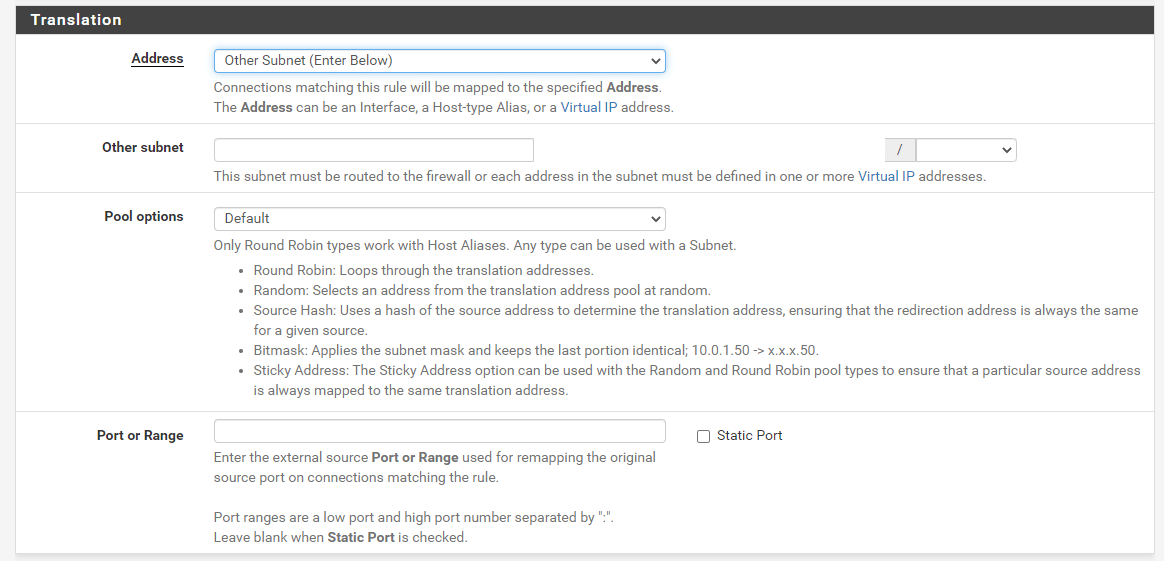
Figure 21. Manual Outbound NAT Rule Translation Options
-
Port: Specifies the source port to be used for translation. This is often left blank, but may be necessary if the client chooses a random source port while the server needs a specified source port.
-
Static Port: When the source IP address has been translated, maintains the original source port of client traffic. Certain protocols need it, such as IPsec without NAT-T, while others, such as SIP and RTP, function better with it. By selecting this option, the Port input box is disabled.
-
No XML-RPC Sync: This option is only applicable if a HA Cluster setup is in use; otherwise, it should be omitted. Checking this option while using a HA cluster with configuration synchronization will prevent the rule from being synchronized to the other cluster members. Generally, though, all rules should be synchronized. This option only applies to major nodes and does not prevent rules from being overridden on secondary nodes.
-
Description: A reference to an optional text that explains the intent of this rule.
These rules can fit the majority of NAT scenarios, regardless of size.
How to Monitor Outbound NAT Rules Change?
An outgoing NAT entry receives a timestamp indicating when it was generated or last modified. This timestamp displays the user who generated the rule and the most recent user to modify the rule. On moving from Automatic Outbound NAT mode to Manual Outbound NAT mode, the established rules are identified as having been generated by this procedure.
How to Select a NAT Configuration?
The optimal NAT setup for a specific deployment is mostly determined by the number of accessible public IP addresses and the number of local services that need inbound Internet connection.
-
Single Public IP Address for Each WAN: When just one public IP address is accessible per WAN, NAT choices are restricted. WAN IP addresses are compatible with 1:1 NAT rules, however this might have downsides. In this instance, port forwarding is the ideal method.
-
Multiple Public IP Addresses per WAN: When multiple public IP addresses are accessible per WAN, various incoming and outgoing NAT setup options are possible. Depending on the requirements of the site, port forwarding, 1:1 NAT, and Hybrid or Manual Outbound NAT may be desired.
What is NAT Compatibility and Protocol Compatibility?
Certain protocols do not function well with NAT, while others do not function at all. Problematic protocols contain IP addresses and/or port numbers into packets (e.g., SIP and FTP); others do not function correctly if the source port is altered (e.g., SIP from a PBX and IPsec); and pf is problematic because to its limits (PPTP). This section describes a selection of protocols that are incompatible with NAT in the pfSense® software, along with workarounds:
Online Gaming
Games are mostly NAT-friendly, with a few exceptions. This section discusses both online-capable PC games and console gaming platforms. This section summarizes the experiences of many pfSense software users.
-
Static Port: A static port must be configured on outbound NAT rules for some games to operate correctly. If a game is having trouble establishing a connection, the recommended first step is to enable static port for console communication.
-
Several players or devices behind a Network Address Translation (NAT) router: When numerous players or devices are located behind a single NAT device, certain games have problems. These difficulties seem to be NAT-specific, not pfSense-specific, since users who have tried different firewalls have the same issues.
-
Solving NAT problems with UPnP: Several recent gaming systems allow Universal Plug-and-Play (UPnP) to establish NAT port forwarding and firewall rules automatically. Often, enabling UPnP on pfSense software will enable games to function with few or no involvement.
FTP
As a result of its architecture, FTP is incompatible with both NAT and firewalls. FTP was created in the 1970s, and the present standard outlining the protocol's requirements was produced in 1985. As FTP was developed more than a decade before NAT and long before firewalls were commonplace, it behaves in a manner that is very hostile to NAT and firewalls.
The basic installation of pfSense does not contain an FTP proxy, however a client proxy is available as an add-on package.
FTP Restrictions
Since pf lacks the capability to adequately handle FTP traffic without a proxy and the FTP proxy package implementation is relatively deficient, FTP use is restricted.
FTP servers behind NAT
For FTP servers behind NAT, all relevant ports must be forwarded manually and authorized under firewall rules. Instead, in the case of 1:1 NAT, just the firewall rules are required. Depending on the FTP method, server software, and client software, it may be necessary to configure the server.
FTP modes
FTP may operate in different modes that alter the client and server's behavior, as well as which side waits for new connections. The complexity of NAT and firewall rules depends on these modes and whether a distant client is trying to connect to a server behind pfSense or a local client is attempting to connect to a remote server.
Active Mode
While in Active Mode With FTP, when a file transfer is requested, the client listens on a local port and then communicates its IP address and port number to the server. The server will reconnect to the specified IP address and port to send the data. This is a difficulty for firewalls due to the often random nature of the port, while current clients allow for the limitation of the port range. In the event of a client behind NAT, the provided IP address would be a local address that cannot be reached by the server. In addition, a firewall rule and port forward permitting traffic into this port would need to be implemented.
When the FTP proxy package is enabled and a client behind pfSense software connects to a remote server, the proxy tries to accomplish three primary tasks: Then, it modifies the FTP PORT command such that the IP address is the WAN IP address of the firewall and a random port on that IP address. Next, it installs a port forward that links the translated IP address and port to the FTP client's original IP address and port. Lastly, it permits FTP server traffic to connect to the "public" port. Multi-WAN restricts the proxy's functionality to the WAN containing the default gateway.
When everything is functioning well, this occurs invisibly. The server is unaware that it is communicating with a client behind NAT, and the client is unaware that the server is not connected directly.
Active mode is often not an issue for a server behind NAT, since the server will just listen for connections on the conventional FTP ports and then make outbound connections to the clients. The outbound firewall rules must let the server to establish arbitrary outbound connections, and those connections must not be routed out a WAN other than the one that accepted the incoming FTP connection.
Passive Mode
Passive Mode (PASV) essentially functions in reverse. Since the server rather than the client listens on a port when a file transfer is requested, it is more NAT- and firewall-friendly for clients. PASV mode will often function for FTP clients behind NAT without the need of a proxy or any extra processing.
When a client requests PASV mode, the server will supply the client with its IP address and a random port on which the client may try to connect. This IP address and port must be translated and permitted via the firewall since the server is on a private network. The FTP server must offer the public IP address to which clients connect, although certain clients, such as Filezilla, are intelligent enough to disregard a private IP address and connect to the original server IP address.
Extended Passive Mode
Extended Passive Mode (EPSV) functions similarly to PASV mode, but supports IPv6. When a client requests a transfer, the server will respond with the connection port. The same restrictions apply as with servers in PASV mode.
FTP Hosts and Forwarding Ports
For FTP servers offering passive mode to clients, the FTP server setup must establish a passive port range and configure the external NAT address, which is often the WAN IP address of the firewall. The method for configuring these settings depends on the FTP server software implementation. The passive port range must be routed using port forwards together with TCP port 21 on the firewall.
For FTP servers offering active mode to clients, only TCP port 21 requires a port forward.
FTP Servers and 1:1 NAT
The firewall rules must permit port 21 and the passive port range for 1:1 NAT.
TFTP
Normal TCP and UDP traffic begins connections to distant sites using a random source port within the ephemeral port range, which varies by operating system but falls between 1024 and 65535, and the destination port of the protocol in use. Responses from server to client invert the preceding: The source port is the destination port for the client, and the destination port is the source port for the client. This is how pf associates reply traffic with inbound connections.
TFTP (Trivial File Transfer Protocol) does not, however, adhere to this norm. RFC 1350, the standard defining TFTP, states that the server's response to the client will originate from a pseudo-random port number. The TFTP client may choose port 10325 as the source port and port 69 as the destination port. The server for other protocols would then send the reply using port 69 as the source port and port 10325 as the destination port. Due to the fact that TFTP employs a pseudo-random source port, the reply traffic will not match the state that pf has constructed for this traffic. Hence, the responses will be prohibited since they seem to be unwanted Internet traffic.
TFTP is not a prevalent protocol on the Internet. Certain IP phones that connect to external VoIP providers over the Internet utilizing TFTP to get settings and other information are the only occurrences where this is sometimes a problem. The majority of VoIP providers do not demand this.
If TFTP traffic is required to traverse the firewall, a TFTP proxy may be setup under System > Advanced > Firewall & NAT tab.
PPTP / GRE
The inability of pf to NAT the GRE protocol is the reason of PPTP's restrictions in the pfSense software. As a result, the constraints apply to any usage of the GRE protocol, but PPTP has been the most prevalent application in the wild.
The GRE protocol state tracking code in pf can only monitor one session per public IP address per external server. This implies that if a PPTP VPN connection is established, only one internal system may connect to the same PPTP server on the Internet concurrently. A thousand computers can concurrently connect to a thousand distinct PPTP servers, but only one can connect to a single server. Moreover, a single client may connect to an infinite number of remote PPTP servers.
Using several public IP addresses on the firewall, one per client through Outbound or 1:1 NAT, or multiple public IP addresses on the external PPTP server is the only feasible workaround. This is not an issue with other VPN connection types.
Owing to the very poor security of PPTP, including a total compromise of the whole protocol, its use should be halted immediately; hence, this problem is irrelevant given the current security requirements.